
Programming instructions

4000 Series ICs
National Instruments Corporation 7-11 Multisim Component Reference Guide
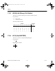
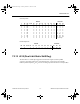
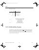
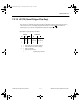
7.2.19 40175 (Quad D-type Flip-flop)
Quadruple D-type flip-flop truth table:
This device is a quadruple edge-triggered D-type flip-flop with four data inputs (D
0
to D
3
),
a clock input (CP), an overriding asynchronous master rest input (MR
), four buffered
outputs (Q
0
to Q
3
), and four complementary buffered outputs (Q
0
to Q
3
).
INPUTS OUTPUTS
CP D MR
QQ
11 1 0
01 0 1
X 1 no change no change
XX0 0 1
1 = HIGH state (the more positive voltage)
0 = LOW state (the less positive voltage)
X = state is immaterial
= positive-going transition
= negative-going transition
ComponentRef.book Page 11 Thursday, December 7, 2006 10:12 AM