
Programming instructions

TTL
Multisim Component Reference Guide 6-90 ni.com
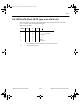
HIGH, the outputs do not change state regardless of the data or clock inputs transitions. This
device is ideal for parity bus interfacing in high performance systems.
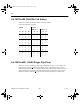
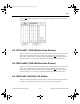
6.4.15674xx825 (8-Bit D-Type Flip-Flop)
This device consists of eight D-type edge-triggered flip-flops. This device has 3-STATE true
outputs and is organized in broadside pinning. In addition to the clock and output enable pins,
the buffered clock (CP) and buffered Output Enable (OE
) are common to all flip-flops. The
flip-flops will store the state of their individual D inputs that meet the setup and hold times
requirements on the LOW-to-HIGH CP transition. With the OE
LOW the contents of the flip-
flops are available at the outputs. When the OE
is HIGH, the outputs go to the high impedance
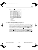
state. Operation of the OE input does not affect the state of the flip-flops. The 74F825 has
Clear (CLR
) and Clock Enable (EN) pins. When the CLR is LOW and the OE is LOW the
outputs are LOW. When CLR
is HIGH, data can be entered into the flip-flops. When EN is
LOW, data on the inputs is transferred to the outputs on the LOW-to-HIGH clock transition.
ComponentRef.book Page 90 Thursday, December 7, 2006 10:12 AM