
Programming instructions

Transistors
Multisim Component Reference Guide 4-22 ni.com
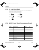
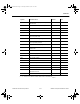
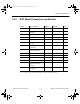
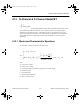
4.12.2 GaAsFET Parameters and Defaults
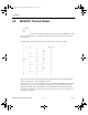
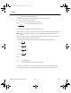
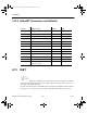
4.13 IGBT
The IGBT is an MOS gate-controlled power switch with a very low on-resistance. It is similar
in structure to the MOS-gated thyristor, but maintains gate control of the anode current over a
wide range of operating conditions.
The low on-resistance feature of the IGBT is due to conductivity modulation of the n epitaxial
layer grown on a p
+
substrate. The on-resistance values have been reduced by a factor of
Symbol Parameter name Default Unit
VTO Pinch-off voltage -2 V
BETA Transconductance 0.0001 A/V
2
B Doping tail extending parameter 0.3 1/V
ALPHA Saturation voltage 2 1/V
LAMBDA Channel-length modulation 0 1/V
RD Drain ohmic resistance 0 W
RS Source ohmic resistance 0 W
CGS Zero-bias G-S junction capacitance 0 F
CGD Zero-bias G-D junction capacitance 0 F
PB Gate junction potential 1 V
KF Flicker noise coefficient 0 -
AF Flicker noise exponent 1 -
FC Coefficient for forward-bias depletion
capacitance formula
0.5
ComponentRef.book Page 22 Thursday, December 7, 2006 10:12 AM