
Programming instructions
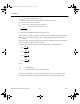

JFETs (Junction FETs)
National Instruments Corporation 4-19 Multisim Component Reference Guide
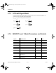
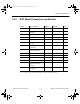
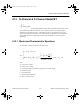
4.9.2 JFET Model Parameters and Defaults
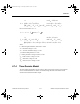
r
D
= r
S
= 10% to 15% of the on-state drain-to-source resistance, R
DS(on)
.
Symbol Parameter Name Default Example Unit
VTO Threshold voltage -2 -2 V
BETA Transconductance
coefficient
0.0001 1e-03 A/V
LAMBDA Channel-length modulation 0 1e-04 1/V
2
RD Drain ohmic resistance 0 100 W
RS Source ohmic resistance 0 100 W
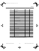
IS Gate-junction saturation
current
1e-14 1e-14 A
Cgd Zero-bias gate-drain junction
capacitance
0 1e-12 F
Cgs Zero-bias gate-source
junction capacitance
0 5e-12 F
PB Gate-junction potential 1 .06 V
B Doping tail parameter 1 1.1 -
KF Flicker noise coefficient 0 - -
AF Flicker noise exponent 1 - -
FC Coefficient for forward-bias
depletion capacitance
formula
.5 - -
TNOM Parameter measurement
temperature
27 50 °C
ComponentRef.book Page 19 Thursday, December 7, 2006 10:12 AM