
Programming instructions

JFETs (Junction FETs)
National Instruments Corporation 4-17 Multisim Component Reference Guide
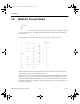
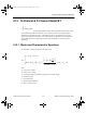
4.9 JFETs (Junction FETs)
The JFET is a unipolar, voltage-controlled transistor that uses an induced electrical field to
control current. The current through the transistor is controlled by the gate voltage. The more
negative the voltage, the smaller the current.
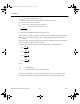
A JFET consists of a length of an n-type or p-type doped semiconductor material called a
channel. The ends of the channel are called the source and the drain. The terminal with the
arrowhead represents the gate.
In an n-channel JFET, the gate consists of p-type material surrounding the n-channel. In a p-
channel JFET, the gate consists of n-type material surrounding the p-channel.
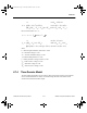
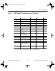
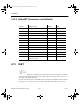
4.9.1 DC Model
The DC model characteristic is determined by a nonlinear current source, I
D
.
Forward characteristics (
V
DS
≥ 0):
Reverse characteristics (
V
DS
< 0):
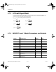
where:
V
GS
= gate-source voltage, in volts
V
DS
= drain-source voltage, in volts
V
GD
= gate-drain voltage, in volts
00
10
210
2
for
for
for
()
()() ()
([( ) ]( ) ( )
VV
IVV V VVV
VVVV V V VV
GS TO
D GSTO DS GSTO DS
DS GS TO DS DS DS GS TO
−≤
=− − + < − ≤
−− + <≤−
βλ
βλ
00
10
210
2
for
for
for
()
()() ()
([( ) ]( ) ( )
VV
IVV V VVV
VVVV V V VV
GS TO
D GSTO DS GSTO DS
DS GS TO DS DS DS GS TO
−≤
=− − + < − ≤
−− + <≤−
βλ
βλ
ComponentRef.book Page 17 Thursday, December 7, 2006 10:12 AM