
Programming instructions

Transistors
Multisim Component Reference Guide 4-16 ni.com
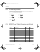
4.8 MOSFET Thermal Model
This is an interactive device that lets you simulate the heat generated in a MOSFET. Pressing
“T” on your keyboard lets you toggle the displayed parameter between Junction, Dielectric
Bond and Case.
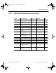
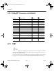
The following thermal electrical equivalent circuit represents the device’s model.
Heat generated in a device’s junction flows from a higher temperature region through each
resistor-capacitor pair to a lower temperature region.
PDiss is a current source; its amplitude is the power consumed by the MOSFET. The voltages
of the nodes T
J
, T
B
, T
C
and T
A
represent the temperature rise of the junction point of the
MOSFET, dielectric bond of the MOSFET, case of the MOSFET and ambient temperature.
The ambient temperature is considered constant (no temperature rise), so the voltage of T
A
is
zero and T
A
is grounded.
T
J
T
B
T
C
T
A
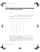
ComponentRef.book Page 16 Thursday, December 7, 2006 10:12 AM