
Programming instructions

Transistors
Multisim Component Reference Guide 4-14 ni.com
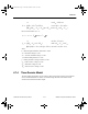
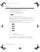
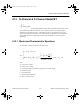
4.7.5 AC Small-Signal Model
In the linearized small-signal model, the junction diodes used to model the MOSFETs are
replaced by their equivalent small-signal models.
C
GB
,
C
GS
,
C
GD
are zero-bias junction capacitances.
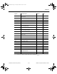
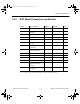
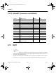
4.7.6 MOSFET Level 1 Model Parameters and Defaults
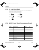
g
dI
dV
g
dI
dV
g
dI
dV
g
dI
dV
g
dI
dV
m
D
GS
OP BS
BS
BS
OP
DS
D
GS
OP BD
BD
BD
OP
mBS
D
BS
OP
==
==
=
Symbol Parameter Name Default Unit
VTO Threshold voltage 0 V
KP Transconductance coefficient 2e-05 A/V
2
LAMBDA Channel-length modulation 0 1/V
PHI Surface potential 0.6 V
GAMMA Bulk-threshold parameter 0 V**0.5
RD Drain ohmic resistance 0 W
RS Source ohmic resistance 0 W
IS Bulk-junction saturation current 1e-14 A
CGBO Gate-bulk overlap capacitance per meter
channel length
0F
CGDO Gate-drain overlap capacitance per meter
channel length
0F
ComponentRef.book Page 14 Thursday, December 7, 2006 10:12 AM