
Programming instructions

BJT (NPN & PNP)
National Instruments Corporation 4-5 Multisim Component Reference Guide
and for the base-collector junction, C
BC
and C
JX
,
The symbols used in these equations are defined in “BJT Model Parameters and Defaults.”
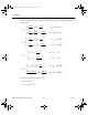
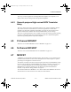
4.1.3 AC Small-Signal Model
The small-signal model of a BJT is automatically computed during linearization of the DC
and large-signal time-domain models. The circuit shown is the Gummel-Poon small-signal
model of an NPN transistor.
where:
g
p
= input conductance
g
µ
= reverse feedback conductance
g
m
= transductance
g
o
= output conductance.
()
()
FFC
FFCm
m
C
C
2
1
3
1
11
=−
=− +
+
CC g
I
V
CC g
I
V
CC g
I
V
CC
g
g
igv gv
BE OP
B
OP
BC OP m
C
OP
ssubOP
c
A
OP
JX OP ac
m
cbece
JX
ππ
µ
π
πµ
β
==
==
==
=
=+
Τ
Τ
0
ComponentRef.book Page 5 Thursday, December 7, 2006 10:12 AM