
Programming instructions

Transistors
Multisim Component Reference Guide 4-2 ni.com
4.1.1 Characteristic Equations
where:
β
DC
= h
FE
= DC current gain
β
AC
= h
fe
= small-signal current gain
I
C
= collector current
I
B
= base current
∆
I
E
= emitter current
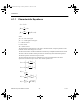
The model for the PNP transistor is the same as the NPN model, except the polarities of the
terminal currents and voltages are reversed.
The DC characteristic of a BJT in Multisim is modeled by a simplified Gummel-Poon model.
The base-collector and base-emitter junctions are described by their ideal diode equations.
The diode capacitors are treated as open circuits.
The beta variation with current is modeled by two extra non-ideal diodes. The diode
capacitors are treated as open circuits. The various equations are:
III
I
I
h
I
I
OP V h
ECB
DC
C
B
FE
AC
C
B
CE fe
=+
==
== =
β
β
∆
∆
()
()
II
V
nV
II
V
nV
K
K
I
IKF
V
V
K
K
K
BE SE
BE
e
BC S
BC
c
q
V
VA
q
SBE
qb
q
q
BC
2
2
1
2
1
2
1
1
1
1
1
2
114
=
−
=
−
=
−
=
−
=++
exp
exp
exp
Τ
Τ
Τ
ComponentRef.book Page 2 Thursday, December 7, 2006 10:12 AM