
Programming instructions

Diodes
Multisim Component Reference Guide 3-16 ni.com
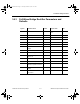
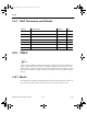
3.9.3 DIAC Parameters and Defaults
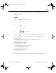
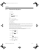
3.10 TRIAC
A triac is a three-terminal five-layer switch capable of conducting current in both directions.
The triac model consists of two SCRs, each of which is modeled as described earlier in this
chapter. The triac remains off, restricting current in both directions until the voltage across the
triac exceeds the breakover voltage, or until a positive pulse of current is applied to the gate
terminal.
3.10.1 Model
The simulation is a combined electrical/behavioral model. The status of the triac, either on or
off, is treated as a logical variable. The resistance,
R
s,
is a function of the triac status.
Symbol Parameter Name Default Unit
IS Saturation current 1e-06 A
Vs Switching voltage 100 V
Vtm Peak on-state voltage 1.5 V
Itm Forward current at which Vtm is measured 1 A
Tq Turn-off time 1e-06 s
Ih Holding current 0.02 A
CJO Zero-bias junction capacitance 1e-12 F
ComponentRef.book Page 16 Thursday, December 7, 2006 10:12 AM