
Programming instructions

Diodes
Multisim Component Reference Guide 3-14 ni.com
3.8.3 AC Small-Signal Model
In the AC model, the diode is represented by its linearized small-signal model. The diode
small-signal conductance g
d
and the small-signal capacitance Cd are evaluated at the DC
operating point.
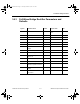
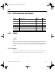
3.8.4 SCR Parameters and Defaults
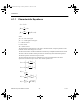
3.9 DIAC
A diac is a two-terminal parallel-inverse combination of semiconductor layers that allows
triggering in either direction. It functions like two parallel Shockley diodes aligned back-to-
back. The diac restricts current flow in both directions until the voltage across the diac
exceeds the switching voltage. Then the diac conducts current in the direction of the voltage.
Symbol Parameter Name Default Unit
Irdm Peak off-state current 1e-06 A
Vdrm Forward breakover voltage 200 V
Vtm Peak on-state voltage 1.5 V
Itm Forward current at which Vtm is measured 1 A
Tq Turn-off time 1.5e-05 s
dv/dt Critical rate of off-state voltage rise 50 V/
µ
s
Ih Holding current 0.02 A
Vgt Gate trigger voltage 1 V
Igt Gate trigger current 0.001 A
Vd Voltage at which Igt is measured 10 V
ComponentRef.book Page 14 Thursday, December 7, 2006 10:12 AM