
Programming instructions
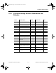
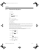

Silicon-Controlled Rectifier
National Instruments Corporation 3-13 Multisim Component Reference Guide
3.8.1 Model
The SCR is simulated using a mixed electrical and behavioral model.
The status of the SCR is handled with a logical variable, much like the Shockley diode and
diac simulations. The resistance,
R
s,
acts as a current block when the SCR is switched off. R
s
has two separate values, depending on the status of the SCR. When the SCR is on, the
resistance
R
s
is low; when the SCR is off, the resistance R
s
is high. The high resistance value
acts as a current block.
The SCR is switched on and
R
s
set low (1e-06) if:
Vd
≥
Vdrm
or
Ig
≥
Igt at Vg
≥
Vgt and
Vd
≥
0
or
of the SCR
The SCR is switched off and
R
s
set high if:
Id < Ih
In this case, the switching occurs after turn-off time T
q
,
which is implemented by the
behavioral controller.
I
d
= current through the SCR, in amperes
r
s
= blocking resistance, in ohms
Symbols used in these equations are defined in “SCR Parameters and Defaults”.
3.8.2 Time-Domain Model
For the time-domain model, the charge-storage effects of the SCR junction capacitance are
considered in the simulation.
The turn-off time,
T
q,
is implemented by introducing a behavioral delay in the opening of the
controlled switch.
dV
dt
dV
dt
d
≥
ComponentRef.book Page 13 Thursday, December 7, 2006 10:12 AM