
Programming instructions


Diodes
Multisim Component Reference Guide 3-10 ni.com
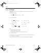
3.6 Full-Wave Bridge Rectifier
The full-wave bridge rectifier uses four diodes to perform full-wave rectification of an input
AC voltage. Two diodes conduct during each half cycle, giving a full-wave rectified output
voltage. The top and bottom terminals can be used as the input terminals for the AC voltage.
The left and right terminals can be used as the output DC terminals.
3.6.1 Characteristic Equation
The average output DC voltage at no load condition is approximately given by:
V
DC = 0.636 * (Vp - 1.4)
where:
V
p
= the peak value of the input AC voltage
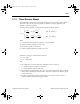
3.6.2 Model
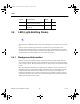
A full-wave bridge rectifier consists of four diodes as shown in its icon.
Terminals 1 and 2 are the input terminals, so the input AC source is connected across 1 and 2.
Terminals 3 and 4 are the output terminals, so the load is connected across 3 and 4.
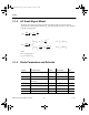
When the input cycle is positive, diodes D
1
and D
2
are forward-biased and D
3
and D
4
are
reverse-biased. D
1
and D
2
thus conduct current in the direction shown. The voltage developed
is identical to the positive half of the input sine wave minus the diode drops.
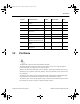
When the input cycle is negative, diodes D
3
and D
4
become forward-biased and conduct
current in the direction shown. Hence, the current flows in the same direction for both the
positive and the negative halves of the input wave. A full-wave rectified voltage appears
across the load.
ComponentRef.book Page 10 Thursday, December 7, 2006 10:12 AM