
Programming instructions

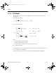
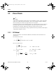

Zener Diode
National Instruments Corporation 3-7 Multisim Component Reference Guide
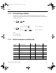
where:
I
D
= current through the diode in amperes
V
D
= voltage across the diode in volts
V
T
= thermal voltage (= 0.0258 volts at room temperature (27°C))
BV = breakdown voltage
I
S
is equivalent to the reverse saturation current (I
o
) of a diode. In a real diode, I
S
doubles for
every 10-degree rise in temperature.
Other symbols used in these equations are defined in the table below.
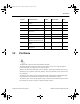
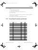
3.3.2 Zener Diode Parameters and Defaults
Symbol Parameter name Default Unit
Is Saturation current 1e-14 A
Rs Ohmic resistance 0 W
CJO Zero-bias junction capacitance 0 F
VJ Junction potential 1 V
TT Transit time 0 S
M Grading coefficient 0.5 -
VZT Zener test voltage 1e+30 V
IZT Zener test current 0.001 A
N Emission coefficient 1 -
EG Activation energy 1.11 eV
XTI Temperature exponent for effect
on Is
3.0 -
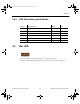
Symbol Parameter name Default Unit
KF Flicker noise coefficient 0 -
AF Flicker noise exponent 1 -
ComponentRef.book Page 7 Thursday, December 7, 2006 10:12 AM