
Programming instructions


Diodes
Multisim Component Reference Guide 3-4 ni.com
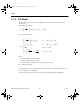
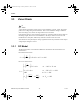
3.1.4 AC Small-Signal Model
The figure below shows the linearized, small-signal diode model, in which the diode is
represented by a small-signal conductance, g
D
.
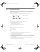
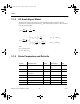
The small-signal capacitance is also evaluated
at the DC operating point.
where:
OP = operating point
Q
D
= the charge on C
D
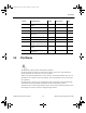
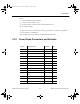
3.1.5 Diode Parameters and Defaults
g
dI
dV
I
nV
eD
D
D
OP
S
V
nV
D
T
==
Τ
C
dQ
dV
gC
V
VFCj
g
C
F
F
mV
VFCj
D
D
D
OP
tj
D
D
t
j
D
D
==
∗
<∗
∗+
≥∗
τ
ϕ
τ
ϕ
D
0
-m
D
0
+ -
+
for
for
00
0
2
30
1
Symbol Parameter Name Default Typical Value Unit
IS Saturation current 1e-14 1e-9 - 1e-18 cannot
be 0
A
RS Ohmic resistance 0 10 W
CJO Zero-bias junction
capacitance
0 0.01-10e-12 F
VJ Junction potential 1 0.05-0.7 V
TT Transit time 0 1.0e-10 s
M Grading coefficient 0.5 0.33-0.5 -
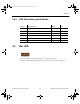
Symbol Parameter Name Default Typical Value Unit
ComponentRef.book Page 4 Thursday, December 7, 2006 10:12 AM