
Programming instructions


Basic Components
Multisim Component Reference Guide 2-36 ni.com
Characteristic Equation and Model
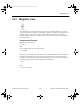
This component’s inductance, L, is computed based on the initial settings according to the
equation:
The variable inductor is simulated as an open circuit with a current across the inductor forced
to zero by a large impedance value.
2.15 Potentiometer
The potentiometer acts much like a regular resistor, except that you can adjust its value using
the keyboard or by hovering the cursor over the device and moving the slider bar that appears.
To set up the potentiometer:
1. Double-click on the potentiometer and select the Val u e tab.
2. Enter the desired maximum resistance for the device in the Resistance (R) field.
3. Enter the Key that will change the potentiometer’s value when pressed.
4. Enter the percentage by which you want the potentiometer to change in the Increment
field.
5. Optionally, enter Component Type and Hyperlink information.
6. Optionally, change the Layout Settings as described below:
•
Edit Footprint button — click to display the Edit Footprint dialog box where you can
select a new
Footprint and Manufacturer.
Note For information on placing resistors and potentiometers, and information on how to
edit footprints, refer to the Multisim User Guide or the Multisim helpfile.
To increase the potentiometer’s value using the keyboard, press the identified key. The
potentiometer’s setting will increase in steps the size of the value entered in the
Increment
field. For example, if the device is a 200k linear potentiometer, and the
Increment is set to 5%,
L
Setting
=
100
* Inductance
ComponentRef.book Page 36 Thursday, December 7, 2006 10:12 AM