
Programming instructions

Basic Components
Multisim Component Reference Guide 2-34 ni.com
4. Enter the percentage by which you want the variable capacitor to change in the Increment
field.
5. Optionally, enter Component Type and Hyperlink information.
6. Optionally, change the Layout Settings as described below:
•
Edit Footprint button — click to display the Edit Footprint dialog box where you can
select a new
Footprint and Manufacturer.
Note For information on placing capacitors and variable capacitors, and information on how
to edit footprints, refer to the
Multisim User Guide or the Multisim helpfile.
To increase the variable capacitor’s value using the keyboard, press the identified key. The
variable capacitor’s setting will increase in steps the size of the value entered in the
Increment
field. For example, if the device is a 200 pF variable capacitor, and the
Increment is set to 5%,
its capacitance will increase by 10 pF steps until it reaches its maximum value of 200 pF.
To decrease the value using the keyboard, press and hold SHIFT and press the identified key.
For example, say the variable capacitor is set to 45%, the increment is 5% and the key is C.
Press C , and the setting increases to 50%. Press C again, and it increases to 55%. Press S
HIFT
and C, and the setting decreases to 50%.
To adjust the variable capacitor’s value using the mouse:
1. Hover the cursor over the device to display its slider bar.
2. Drag the slider to the right to increase the value, or to the left to decrease the value.
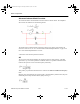
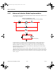
Characteristic Equation and Model
This component’s capacitance, C, is computed based on the initial settings according to the
equation:
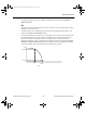
The variable capacitor is simulated as an open circuit with a current across the capacitor
forced to zero by a large impedance value.
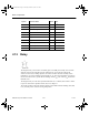
C
Setting
=
100
* Capacitance
ComponentRef.book Page 34 Thursday, December 7, 2006 10:12 AM