
Programming instructions

Nonlinear Transformer
National Instruments Corporation 2-31 Multisim Component Reference Guide
2.11.1 Customizing
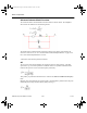
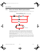
The nonlinear transformer can be customized for different applications. It is implemented by
using a magnetic core and the coreless coil as the basic building blocks. The magnetic core
takes in an input voltage and converts it to a Magnetomotive Force (mmf). The Magnetic
Field Intensity (H) is calculated by dividing the mmf by the Length of the core:
H = mmf/L
H is then used to find the corresponding Flux Density (B). This is done by using the linear
relationship described in the H-B array of coordinate pairs. This H-B array can be taken from
the averaging H-B curve, which may be obtained from a technical manual that specifies the
magnetic characteristics of different cores.
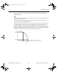
The slope of the B-H function is never allowed to change abruptly, but is smoothly varied
whenever the Input Smoothing domain parameter is set to a number greater than zero.
The Flux Density (B) is multiplied by the cross-sectional area to obtain a Flux Value. The
Flux Value is used by the coreless coil to obtain a value for the voltage reflected back across
the terminals.
The core is modeled to be lossless. No core losses are considered. In the transformer model,
the only losses taken into account are the ones modeled by the winding resistances.
To obtain the H-B points of the curve:
• Contact a manufacturing company. They many be able to provide the technical data
required to model a core.
• Obtain experimental data.
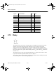
2.11.2 Nonlinear Transformer Parameters and Defaults
Symbol Parameter Name Default Unit
N
1 Primary turns 1 -
R
1 Primary resistance 1e-06 W
L
1 Primary leakage inductance 0.0 H
N
2 Secondary turns 1 -
R
2 Secondary resistance 1e-06 W
L
2 Secondary leakage inductance 0.0 H
ComponentRef.book Page 31 Thursday, December 7, 2006 10:12 AM