
Programming instructions

Transformer
National Instruments Corporation 2-29 Multisim Component Reference Guide
Within the Bmain expression, the segment Lo*(1-0.1/(Idc^2)*i(v1)^2)* v_di_dt is exactly the
inductor equation we desire:
The if-statement switches between the non-linear inductor model and the constant linear
inductor model when the inductance falls to 10% of nominal value (or current has reached
3*Idc).
References
[1] Martin O’Hara, “Modeling Non-Ideal Inductors in SPICE, Martin O’Hara,” EETimes
Asia, April 2002
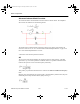
2.10 Transformer
The transformer is one of the most common and useful applications of inductance. It can step
up or step down an input primary voltage (V1) to a secondary voltage (V2). The relationship
is given by V1/V2 = n, where n is the ratio of the primary turns to the secondary turns. The
parameter n can be adjusted by editing the transformer's model.
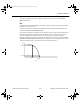
To properly simulate the transformer, both sides must have a common reference point, which
may be ground. The transformer can also be used in a center-tapped configuration. A
center-tap is provided which may be used for this purpose. The voltage across the tap is half
of the total secondary voltage.
This transformer is suitable for getting quick results. To simulate realistic devices that include
a transformer, you should use the nonlinear transformer.
Note Both sides of a transformer must be grounded.
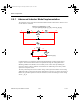
2.10.1 Characteristic Equation
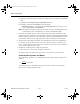
The characteristic equation of an ideal transformer is given by:
VnV
i
n
i
12
12
1
=
=
ComponentRef.book Page 29 Thursday, December 7, 2006 10:12 AM