
Programming instructions

Basic Components
Multisim Component Reference Guide 2-28 ni.com
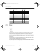
2.9.1 Advanced Inductor Model Implementation
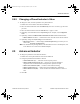
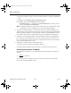
The schematic version of the advanced inductor SPICE model is shown below. Nodes 1 and 2
are the inductor's terminals.
Components Rdc, Cp, and Rp are parasitics that model the DC resistance and frequency
response. The actual non-linear inductor is implemented using the Analog Behavioral
Modeling (ABM) source, Bmain, and a secondary circuit. This is done by modeling the
derivative operator, which is inherent to the inductor I/V relationship, with a unity-valued
capacitor in a separate circuit.
The unity-valued capacitor is driven with a voltage value equal to the inductor current using
ABM source B2, by referencing the current through the 0-volt source V1. In the expression of
Bmain, the generated capacitor current (the derivative) is referenced through a 0 volt voltage
source, v_di_dt.
Rdc
Rp
Cp
Bmain 3 4 V={if(abs(i(v1)) < 3*Idc ,
+Lo*(1-0.1/(Idc^2)*i(v1)^2)* i(v_di_dt), Lo*0.1*i(v_di_dt))}
Bmain
ABM
4
V1
0 V
123
C1
1F
B2
ABM
v_di_dt
0 V
0
56
B2 6 0 V={i(v1)}
ComponentRef.book Page 28 Thursday, December 7, 2006 10:12 AM