
Programming instructions

Basic Components
Multisim Component Reference Guide 2-26 ni.com
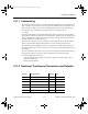
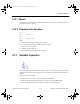
Advanced Inductor Model Overview
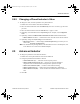
The advanced inductor model includes both non-ideal AC and DC effects. The simplified
subcircuit for the inductor has the following model:
The actual inductor model includes a dependent voltage source that is proportional to the
derivative of the current, I
L
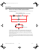
. See “Advanced Inductor Model Implementation” on page 2-28
for a more detailed implementation overview.
A discussion of the model’s parameters follows.
AC
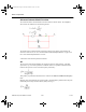
The AC aspect of the model simulates the capacitive behavior of the inductor. A parallel
capacitance, Cp, is inserted in parallel to model this effect. The parallel combination of the
inductor and capacitor create a resonant frequency defined by:
This quantity is specified in datasheets and is entered in the
Inductor Self Resonant Frequency
field.
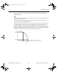
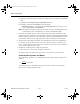
Magnetic loss, which dampens the resonant peak, is modeled with a parallel resistor, Rp. The
relationship between Rp and the inductor quality factor Q, is:
ComponentRef.book Page 26 Thursday, December 7, 2006 10:12 AM