
Technical data


11
Installation
The following section shows typical installations for single
skin, bunded and underground fuel tanks. Full installation,
operation and maintenance instructions are supplied with
each tank.
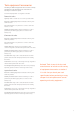
Single skin tanks
A typical single skin fuel oil storage tank installation
Compacted hardcore
300mm min 300mm min
300mm min
300mm min
Non-fire rated wall of building
Non-fire rated boundary
760mm min
1.8m min
Fire Prevention Clearances
Tank to be installed in
accordance with the
requirements of BS5410 and
simplified in OFTEC document
TI14.
Expansion Clearance
Tank must be installed with
clearance of 150mm all round
to allow for expansion when
full of fuel.
Tank Support Base
Base must fully support the
tank with no overhangs or gaps.
Tanks providing fuel oil to
domestic users (single family
dwellings with a capacity of
less than 3500ltrs) must comply
with the requirements of
OFTEC Technical Book 3:
Section 2.7. An OFTEC
registered engineer can provide
full details.
Base
100mm thick 1:2:4 concrete
mix or 65x215mm precast
concrete lintels to BS 5977 or
50mm thick paving slabs
Note: Large tanks require
thicker bases. Consult OFTEC
or an OFTEC registered
engineer for advice.
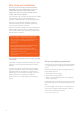
Q Position the tank ensuring best access for filling, maintenance and safety
Q Ensure that the tank support structure is suitable for the long term support of
a tank when full. If in doubt seek the advice of an engineer
Q Store in an upright position, support the entire base of the tank on a firm,
flat, level surface ensuring that the area is free from any sharp stones or
other debris
Q Leave sufficient space between the tank and any surrounding structures to
allow for any expansion during filling. We recommend a minimum of 300mm
(12”) all round. Also allow space above the tank for any hinged access covers
to fully open
Q
nsure the tank is protected from strong wind (especially when empty). If
necessary strap it down. Be careful not to induce too much force when tying
down as to distort product shape
Q Connect all pipework, fittings and accessories. The tank and the integrity of
seals could be affected if pipework and fittings are not sufficiently supported
Q Use PTFE tape or Stag compound for jointing
Q Do not exceed the maximum torque rating for your outlet fitting:
- Standard 1” BSP (female) outlet fitting 61Nm (45 lb/ft)
- Special Order 1.5” & 2” BSP female outlet fittings - 67Nm (50 lb/ft)
This information is provided as general guidance.
Specific site conditions may require adjustment to
what is outlined in this brochure. In all cases advice
should be sought from a qualified civil engineer.