
Service manual


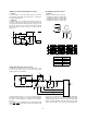


(10) Copy lamp control section
The change in the copy lamp exposure level is adjusted by changing
the ON period duty of the output pulse (CLPUM) from the CPU and
controlling the copy lamp voltage. Fig. 1 and Fig. 2 show the circuit
diagram and the waveform.
7
8
1
+
-
IC1128
NJM2901M
FW
R160
47KJ
R161
10KJ
C131
0.01µF
R166
30KF
1
5
BR102
10KJ x 4
1
4
BR102
10KJ x 4
5V2
FWS
C138
1000P
R165
15KF
10
9
8
+
-
IC1128
NJM2901M
R166
30KF
D103
1SS133
R167
15KF
R166
30KF
C107
0.47µF
50V
R169
200KF
R170
82KF
CLV
10
11
13
+
-
IC1120
NJM2901M
DTC114YK
Q107
CLPWM
R171
3.9KF
24V
ZD103
HZ59A3
R173
1KJ
CLPWM
5V2
R202
4.7KJ
C133
0.047µF
D102
1SS133
R174
1KJ
5V2
R175
10KJ
Q108
2SC2411K
Q109
DTA114YK
R105
2.2KJ
1/2W
CL
A
V5
V4
V3
V2
V1
V3'
12 – 9