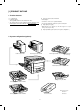
SERVICE MANUAL CODE: 00ZSF1120SM/E SF-1020 MODEL SF-1120 MODEL Option SF-1020 SF-1120 • • • • • • • • Paper tray (SF-UB15) Two-step paper feed unit (SF-CM15) One-step paper feed unit (SF-CM16) Personal counter (SF-71A/71B) 10-bin sorter (SF-S17N) @ 10-bin staple sorter (SF-S54) @ Auto document feeder (SF-A18) @ Reverse automatic document feeder (SF-A57) @ @ For the options, refer to their service manuals. CONTENTS [ 1 ] PRODUCT OUTLINE . . . . . . . . . . . . . . . . . . . . . . . . . . . . . . . . .
Contents [1] PRODUCT OUTLINE . . . . . . . . . . . . . . . . . . . 1-1 1. Product features . . . . . . . . . . . . . . . . . . . . . . . . 1-1 2. System configuration (options) . . . . . . . . . . . . . 1-1 8. Toner supply . . . . . . . . . . . . . . . . . . . . . . . . . . . 4-5 9. Center shift adjustment . . . . . . . . . . . . . . . . . . . 4-7 10. Label attachment . . . . . . . . . . . . . . . . . . . . . . . . 4-7 A. Label attachment . . . . . . . . . . . . . . . . . . .
1-9. Lower paper feed roller/take-up roller . . . 6-3 B. DB blade replacement (Replace every 120K copies.) . . . . . . . . 6-21 2. Transport unit . . . . . . . . . . . . . . . . . . . . . . . . . . 6-3 C. V ring attachment . . . . . . . . . . . . . . . . . . 6-21 2-1. Resist roller, transfer roller . . . . . . . . . . . . 6-3 D. Note for toner hopper drive gear (31T) and stirring shaft attachment . . . . . . . . . 6-21 1-8. Transport roller . . . . . . . . . . . . . . . . . . . . . 6-3 2-2.
2-6. Process section adjustment . . . . . . . . . . 7-21 [8] SIMULATION . . . . . . . . . . . . . . . . . . . . . . . . . . . 8-1 1. Outline . . . . . . . . . . . . . . . . . . . . . . . . . . . . . . . . 8-1 2. Purpose . . . . . . . . . . . . . . . . . . . . . . . . . . . . . . . 8-1 3. Operating procedure . . . . . . . . . . . . . . . . . . . . . 8-1 4. List of simulations . . . . . . . . . . . . . . . . . . . . . . . 8-2 5. Details of simulations . . . . . . . . . . . . . . . . . . . . 8-4 6.
[1] PRODUCT OUTLINE 1. Product features (1) • • Compact body Compact body size The body width of 600mm is the smallest in the class. • (2) Clean copy gentle to the environment Silent design, • Low level of ozone, use of recyclable materials The employment of the front loading tray and the folding-type multi manual paper feed cassette realizes the small occupying area. • The energy-saving mode reduces the power consumption. (3) High capacity of copying Warm-up time is less than 45 sec.
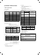
(10) Void width [2] PRODUCT SPECIFICATIONS Void area: Lead edge/rear edge: 3mm or less Image loss Normal: 4mm or less (11) Paper exit/finishing 1.
(2) 2.
3.
Functions 4. Optional specifications (1) Automatic document feeder (ADF) Original detection on the tray Available (For originals of indefinite sizes, scanning is made.
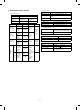
(4) 10-bin staple sorter (10-bin SS) (5) Two-step paper feed unit Type Copier installation type/hanging type Paper size A3 ∼ A5 Distribution system Bin shift system by lead screw Paper feed capacity 250 sheets × 2 steps No. of bins 10 bins (The top bin is commonly used for non-sort.
[3] PRODUCT VIEWS 1. External view and internal structure 6 7 8 1 2 5 3 9 10 4 11 12 13 5 15 17 14 18 16 Upper unit 20 19 Lower unit No. Name No. Name No.
2.
SF-1120 (AB series) 17 1 16 SORTER SORT STAPLE SORT GROUP ORIGINAL TO COPY 2 1 1 EVEN NUMBER ODD NUMBER 2 2 2 EXPOSURE DUAL PAGE COPY ORIGINAL SIZE A3 A4 A4 A5 B4 EX TRA MARGIN SHIFT 1 2 3 4 5 EDGE E RA SE 33 21 3 20 AUTO MANUAL PHOTO 1 1 PRE-COUNT ORIGINALS 15 2 4 5 PAPER SIZE 6 PRESET RATIO 100% 18 19 ORIGINAL SIZE ENTER 34 TRAY SELECT 7 9 10 200% 141% 122% 115% 86% 81% 70% 50% AUTO PAPER SELECT LIGHT DARK 8 ZOOM INTERRUPT 1 2 3 4 5 6 7 8 9 0/ 24 13 POWER S
3. Clutches, solenoids, and motors (Explained with the SF-1120 and the SF-CM15) Clutches and solenoids 10 20 13 25 12 26 9 22 11 23 24 1 15 19 3 2 8 21 4 14 16 5 17 6 18 7 No.
4. PWB (Explained with the SF-1120 and the SF-CM15) 1 2 3 4 5 21 7 6 18 8 20 19 10 9 17 23 11 22 16 15 No Name Description 14 13 No 12 Name Description 1 Operation PWB A Operation input, display control 2 Operation PWB B Operation input, display control 3 Blank lamp PWB Used to control the blank lamp. 4 DL PWB Used to drive the discharge lamp. 5 Optical PWB AE sensor and lens motor interface 6 Process control PWB Used to sense the toner density.
5. Sensors and switches (Explained with the SF-1120 and the SF-CM15) 2 3 5 4 6 29 30 7 31 1 10 28 27 8 9 23 12 11 16 13 17 14 18 15 19 24 25 26 20 21 22 For the ADU sensor, refer to page 5-18. No.
6. Rollers, mirrors, etc. 30 29 28 20 19 18 3 4 17 7 34 16 6 5 8 14 15 12 13 11 9 32 44 33 ADU 45 39 40 31 No. 46 Name 27 26 25 24 23 22 No. 21 43 Name 42 38 41 No. Name 1 No. 3 mirror 2 No. 2 mirror 3 No. 1 mirror 4 Copy lamp 5 No. 4 mirror 6 No. 5 mirror 7 No.
2 Avoid high temperature and high humidity, and avoid sudden temperature change. (Avoid installation near a cooler or a heater.) If not, paper absorbs moisture and dew forms in the machine, causing paper jam or degraded image quality. [4] UNPACKING AND INSTALLATION 1. Unpacking (Standard condition): 20 ∼ 25°C: (Temperature and humidity): The best condition to use the machine.
5 Avoid installation to a poorly ventilated place. (5) Grounding wire connection 1 Connect the grounding wire to prevent against a danger. 2 When connecting the grounding wire, connect only to the grounding object (the grounding terminal of the power outlet, etc.) and never connect to a gas pipe. 6 Avoid installation to a place where there are flammable materials or ammonia gas, etc. If the machine is installed near a diazo copier, the picture quality may be degraded and malfunctions may occur.
3. Optical system lock release 4. Charger cleaning A. No. 2/3 mirror unit lock release A. Main charger unit electrode cleaning Remove the one fixing screw of the No. 2/3 mirror unit on the left side of the copier. 1 Press the hook section of the main charger unit to release lock, and pull out and remove the main charger unit from the copier. Hook Mirror unit fixing screw main charger unit 2 Remove one fixing screw of the main charger unit (on the back side). Fixing screw Electrode section B.
4 Return the electrode section to the original position and fix it with a screw. 3 Remove three fixing screws of the toner hopper of the developing unit, and remove the toner hopper. 5 Insert the main charger unit along the guide groove in the copier fully to the bottom.
6 Hold the hand carry strap of the developing unit and insert it into the copier fully to the bottom. 7. Accessory installation A. Copy tray installation Install the copy tray to the paper exit section on the left side of the copier. Hand carry strap Developing unit Grip 7 Close the developing unit lever and close the front cabinet. Copy tray Developing unit lever 8. Toner supply Front cabinet 1 Open the front cover. With the above procedure, setting of the developing unit is completed. 6.
3 Hold the new toner bottle as shown and shake it four or five times. 6 Close the toner hopper cover. 4 Open the toner hopper cover. 7 Slide the developer unit into the copier. 8 Return the developer unit lock lever into place. 5 Pour the toner evenly into the toner hopper. 9 Close the front cover.
9. Center shift adjustment 10. Label attachment There is basically no need to perform the center shift adjustment because it is made when shipping. If the center should be shifted, adjust in the following procedures. Make a copy. If the center is shifted as shown in Fig. 1 or Fig. 2, loosen the four screws which are fixing the cassette grip cabinet. A. Label attachment Attach the magnification ratio select label packed together with the Operation manual to the position shown in the figure below.
3 The following procedure must be performed by two persons. 11. Optional two-step paper feed unit (SF-CM15) installation Hold the grips of the copier, and insert the positioning bosses (2 positions) of the two-stage paper feed unit into the positioning holes (2 positions) on the bottom of the copier. Then put the four legs of the copier on the two-stage paper feed unit. Grip Parts packed together Grip Positioning boss Connection adjustment plate x 1 pc. Connection screw A x 2 pcs.
Connect the rear side of the copier with two connection screws C. 12. Optional one-step paper feed unit (SF-CM16) Connection screw C Connection screw C Included parts 6 Remove the connecter which is fixed to the rear cabinet of the two-stage paper feed unit with tape. Connect the 4P connector and 10P connector with the 4P connector and 16P connector of the copier.
3. Placing the main copier unit over the paper feed unit [Note] • The following procedure should always be performed by two persons. Lift the main copier unit by the grips and slip the two positioning holes on the bottom of the main copier unit over the two positioning bosses on the paper feed unit, then set the four feet on the main copier unit in their proper places on the paper feed unit.
8. Set the mode. Plug the copier into a grounded outlet and turn the power switch on. • Center line of copy paper Operate the keys on the copier to set the mode. 2 0 C 6 Center of copy image (before adjustment) 0 1 • The above key operation will display the currently set mode.
3. Remove the size block upward, and fit to the suitable paper size. A3 size Hole B4 size A3 Hole B5 size A5 B5 Hole Hole A5 size Hole Hole Special A4 size B4 Hole R Hole size Hole A4 Hole B5 A4R R size B5R Hole Hole When the size is changed to A5, fit the size block display to"Special." Caution • When the tray paper size is changed, be sure to change the size block. If not, the paper size display lamp keeps indicating the previous size. 4. Attach the tray.
3 Optical section In the case of SF-1020: The SF-2020 is provided with the three-way paper feed system. The tray is of the universal type and has capacity of 250 sheets. The front loading system allows the tray to be loaded from the lower side of the front cabinet. (The SF-1120 has the two-way paper feed system with one 250-sheet tray and manual feed.) The tray has the capacity of 500 sheets (250 sheets for the SF-1120).
2. Developing section (Details of DV harness connector) 1) General descriptions For bias For color identification (1) Two-component developer The developer is composed of toner and carrier. Carrier serves as a medium for attaching toner onto the electrostatic image on the photoconductor drum. By stirring toner and carrier, they are rubbed to be charged positive (+) and negative (–) respectively. Since developer will deteriorate to degrade copy quality, it should be replaced regularly.
3) Basic operations (Cassette paper feed) When the CPFC (cassette paper feed clutch) is turned on, the paper feed roller shaft, the paper feed roller, and the take-up roller rotates in the direction of A, and the roller release arm is moved downward by the limiter spring. As a result, the take-up roller falls by its weight to reach the paper surface, feeding the paper. When the CPFC is turned off, the take-up roller is pushed up to the position by the roller release arm spring.
(1) Original table (2) Copy lamp The original table is fixed. The original is set in the left center position. 100V series: 85V, 275W 200V series: 170V, 310W (3) Mirror This model uses six mirrors. No. 1 mirror is attached to the copy lamp unit, No. 2/3 mirrors are attached to No. 2/3 mirror base, No. 4/5 mirrors are attached to No. 4/5 mirror base. The copy lamp unit and the No. 2/3 mirror base unit are scanned in copying. The No.
Parts identification and functions Lens home position sensor Mirror home position sensor No. 2/3 mirror unit AE sensor Reflector Copy lamp unit Lens No. 4/5 mirror unit drive motor Mirror motor Copy lamp Lens drive wire No. 4/5 mirror unit Lens Lens unit Mirror base wire Temperature fuse (7) Lens drive shaft (14) Temperature fuse This shaft controls the optical axis of the lens in zoom copy. The lens follows along the slide base shaft. This is to shift the lens unit and the No.
(20) Original size sensing Mirror base scan speed The original size is sensed by the original interruption system. The LED in the rear frame side emits light to the table glass surface. The original interrupts this light, and its size is detected.
(Optical system dirt correction) This model perform dirt correction by changing the copy lamp intensity according to the dirt degree in the optical system (the copy lamp unit, No. 1 mirror, No.2 mirror, No.3 mirror) to prevent against remarkable degrading of copy quality. The reference value is the AE sensor output value which is obtained when the reference plate is exposed with the copy lamp voltage of 67.0V (134.0V) at power ON. This value is checked with sim 44-08, 09.
(4) Copy process This model basic process and structure • The Scorotron method is used to evenly charge the photoconductor surface to the given potential in the charge process. The corona wire regularly used is now replaced with a new corona charge mechanism that employs the 0.1mm thick stainless steel saw teeth plate, in order to suppress ozone generated when the oxide molecule in air is ionized. • Considering the service efficiency, the process separation mechanism is adopted.
(2) Process diagram Original Mirror lens Copy lamp High voltage unit Discharge lamp Blank lamp Exposure Charging Main corona unit Discharge Discharging High voltage unit Toner Development Cleaning blade Waste toner collection Paper exit Developer Cleaning Separation Fusing Manual paper feed Drum upper image/paper synchronization Separation Resist roller Paper feed roller Transportroller Paper cassette Transfer Heat roller Separation corona unit Transfer charger Heater lamp Image
(3) Details of image forming process Step 1 (Main Charging) By negative discharging of the main charger, uniform negative charges are applied to the OPC drum surface. The OPC drum surface potential is controlled by the screen grid voltage to maintain the grid voltage at a constant level.
Low intensity in the area corresponding to the darker density portion of the document Medium intensity in the area corresponding to the medium density portion of the document HIgh intensity in the area corresponding to the lighter density of the document CTL CGL Main corona unit Aluminum layer Blank lamp Discharge lamp OPC drum Developer unit Cleaning blade MG roller Surface potential (High) CTL Surface potential (Medium) CGL Surface potential (Low) Resist roller Seperation pawl Aluminum layer
Step 4 (Transfer) The transfer paper is charged higher than the OPC drum surface potential by strong negative discharge of the transfer charger, making the binding force between the transfer paper and toner stronger than that between the drum and toner, attracting toner to the transfer paper.
Step 6 (Cleaning) Residual toner on the drum is removed by the cleaning blade. The removed toner is sent to the waste toner container by the waste toner transport screw.
(4) Transition of photoconductor surface potential Charge Exposure BL Develop Transfer Separate Clean DL -730V Dark area Developing bias voltage -215V Light area Residual potential (5) Photoconductor drum sensitivity correction In this model, fall in sensitivity due to long use of the photoconductor drum is corrected by the copy lamp light intensity to prevent against considerable change in copy quality.
The grid voltage value where the same density level as the reference level is obtained is displayed by Sim. 44-9 "a". This value is displayed with 50 as the center in the range of 0 ~ 99 in integer numbers. The correction for 50 is 0V (–410V), and the correction for 58 is +30V (–442V). Process control 1 Toner patch images are formed on the photoconductor surface under the three process conditions (MC grid bias voltage).
Waste toner transport mechanism: The waste toner is passed through waste toner transport screw 1 and waste toner pipe 2 to waste toner bottle 3. Waste toner bottle 3 is rotated by the main drive gear via gear 4 to transport toner evenly. When the waste toner bottle is full of waste toner, the rotation torque of gear 4 is increased to escape gear 5 in the arrow direction A, and switch 6 is turned on at the same time to light the waste toner replacement lamp.
5 Drive system division The fuser unit is rotated by the main drive unit. In case of manual rotation of the fuser unit to remove paper jam, however, excessive loads may be applied to the gears. To prevent against this, the pressure of the upper/lower heat rollers is reduced when the machine clamshells are opened. In addition, the fusing gear is so constructed that the drive is not transferred to the drive system.
2 DPTD (DDM rotary encoder sensor) 5 -1 4 3 6 10 9 8 7 5 -2 1 1 DPHPS1 (Alignment plate home position sensor) 2) Details of operation 1 The alignment plate and the rear edge plate detect the home positions, and moves to the paper size position. (ADU motor 1, 2, ON) 2 Paper exit, reverse unit operation (ADU gate solenoid ON) 3 Rollers in the ADU rotate in the direction of paper entry.
(Note for assembly) [6] DISASSEMBLY AND ASSEMBLY 1) There is the 8-pin connector on the back of the rear frame side. When assembling it, carefully insert. The descriptions are divided into the following sections. 1. 2. 3. 4. 5. 6. 7. 8. 9. 10. 11. 2) The belt must be on the paper feed unit gear and the resist roller gear.
(Note for assembly 2) 1-4. Separation roller When attaching the paper feed section roller ass’y, adjust so that the paper feed roller clutch and the PS front roller ass’y clutch projection face toward the paper feed side. 1 Remove the paper feed unit and remove the separation roller. 1-3. PS front roller ass’y 1-5. Paper feed roller, take-up roller 1 Remove the paper feed unit. (For the details, refer to the 1-1.) 1 Remove the paper feed roller, and remove the take-up roller.
(Note for assembly) Attach the paper feed roller so that the one-way clutch is on the rear frame side. (Be careful of the direction.) Attach the roller holder as shown below. One-way clutch side 1-6. Lower paper feed unit 1-8. Transport roller Perform similarly for the optional two-stage paper feed unit. Perform similarly for the optional paper feed unit. 1 Remove the lower paper feed unit. (Refer to 1-6.) Remove two screws and remove the lower paper feed unit.
TC/SC case 4) When attaching the resist roller ass’y to the copier, attach over the upper side of the PS roller lower mylar, then rotate the roller to set the mylar to the normal position. (If the mylar is deformed, it may cause paper jam. Replace it if deformed.) 3 Remove the hook of the front frame side bearing, and lift it up to remove it toward the upper frame side. Remove the rear frame side connector, and slide and remove the resist roller ass’y toward the rear frame side. PS mylar 2-2.
(Note for assembly) 3. Fusing section When removing the unit from the copier, ba careful not to scratch the photoconductor drum and the lower heat roller. Be careful not to break the actuator of the paper exit sensor (POD). 3-1. Fusing unit removal 1 Open the front cover. 3-2. Heater lamp replacement 2 Push the open/close lever down to the right side, and slowly open the upper unit. 1 Remove the fusing cover fixing screw (1 pc.
3-4. Upper separation pawl replacement (Note for assembly) 1 Remove the fusing unit, and remove the cover. Assemble so that the lower separation pawl is on the upper side of the lower heat roller. (At that time, return the separation pawl which was set upright in procedure (2).) 2 Put the fusing unit so that the paper guide is on the lower side of the fusing unit (the separation pawl is on the upper side).
3-7. Thermistor/thermostat removal 1 Remove the fusing unit. (B) 2 Remove the fusing cover, and remove the thermistor/thermostat. Optical adjustment plate * Note for assembly • • Check that the thermistor center is in contact with the heat roller. Clean the thermistor surface with alcohol to remove foreign materials. 4. Optical system The optical system is an integrated finish product delivered by the maker as stated in the previous section.
2 Remove the operation panel, the upper cabinet R, and the right B. Mirror base wire removal cabinet. 1 Remove the upper cabinet L, and the left cabinet. 2 Remove the mirror wire spring from the groove on the left side of the optical base plate. 3 Remove the dark box cover upper. 3 Remove the mirror base wire from the winding pulley. (Remove he wire fixing screw.) 4 Manually move mirror base B. (Within the range where the wire fixing plate fixing screw can be removed.
3 Rotate the mirror base B counterclockwise to remove. 1 Hook the metal fixture of the mirror base wire on the optical base plate hook. 4 Disconnect the connector from the copy lamp unit on the rear 2 Pass the mirror base wire along the groove outside the double frame side and from the No. 2/3 mirror unit. pulley. 5 Rotate the No. 2/3 mirror unit counterclockwise and remove. At the time, put the No. 2/3 mirror unit on the mirror base positioning plate.
2 If the parallelism of the mirror base B is improper as shown in the figure below (one side of the mirror base B is in contact with the positioning plate and the other side is not in contact), perform the following procedure. 2 3 3 Loosen the mirror base drive pulley fixing screw on the side where the mirror base B is not in contact with the positioning plate.
2 Remove the dark box cover upper. 4) Copy lamp unit installation (Mirror base A positioning) This adjustment must be performed in the following cases: • • • When the mirror base drive wire is replaced. When the mirror base A or B is replaced. When any part in the dark box is replaced. When installing the mirror base, reverse the removal procedure of (2)-A. 1 Put the mirror base A in the copier.
5 Remove the drive springs 4 and 5. 8 Remove the drive shafts 4 and 5. * When removing the No. 4/5 mirror unit, remember the positions (scales) of the arrow marks of the drive holder 4 and 5. Zooming rack 6 Remove the zooming rack of the roll holder unit. No.4/5 adjustment screw No.4/5 drive latch stop screw No.4/5 drive holder B. No. 4/5 mirror unit assembly Reverse the above procedures. When attaching the lens drive shaft attachment plate, attach it to position 5 in the above description.
4 Remove drive spring 4 and 5. 6) Lens wire replacement A. Lens wire removal 1 Remove the OR guide L and R, and remove the table glass. 5 Remove the E-ring which is fixing the roll holder drive shaft, and remove the roll holder unit. 2 Remove the dark box cover upper. 6 Remove the zooming cam and the zooming cam drive gear (which are fixed with screws). 3 Remove the lens motor.
7 Remove the drive wire spring and the wire hook from the lens 2. Procedures carriage boss. 1 Manually move the lens carriage unit to fit the lens carriage hole with the optical unit frame hole (which is not the home position hole but the reduction side hole). Insert a pin into the holes, fix the lens unit, and stretch the wire. L drive pulley Lens unit Lens carriage unit Wire SP Wire hook 2 Under the above state, fit the zooming cam drive gear hole with the No.
4 Manually turn the zooming can drive gear to fit the zooming cam 6 Loosen the zooming cam screw, and fit the mark of zooming cam drive gear hole and No. 4/5 mirror drive unit base hole B. drive gear with the mark of No. 4/5 drive shaft. Pin Zooming cam Hole Zooming cam drive gear No. 4/5 mirror drive unit base Zooming cam gear Hole B ∗Do not move the zooming cam gear at this time. Zooming cam drive gear 5 Install No. 4/5 mirror drive shaft unit and the rack.
4 Remove the screw and remove the charging plate (saw teeth) 5. High voltage section ass’y. Clean the MC case, and the TC/SC case every 50K copies. Clean the screen grid, the charging plate (saw teeth), and the TC/SC wire every 50K copies, and replace them every 100K copies. 5-1. Main charger (MC) unit 1 Open the front cover. 2 Hold the MC unit lock section, and pull out the MC unit. (Cleaning/replacement and note) 1 When attaching the screen grid, be careful not to deform and dirt the screen grid.
5 When installing the unit to the body, check that the grounding 5-2. Transfer/separation charger (TC/SC) unit spring is in contact with the TC/SC case (metal section) on the rear and the front sides. (Visually check, and push the center of the TC/SC unit to check that it can be moved up and down.) 1 Open the font cover, open the body up. 2 Push TC/SC unit pawl sections A (2 positions) and lift the front side and pull it out.
4 While pushing waste toner bottle in the direction of A and lift it 6-2. Waste toner bottle replacement (required when waste toner full detection/maintenance) and remove. 1 Take out the process unit as shown above, If the unit is removed by holding the toner transport pipe, toner is spilled. Avoid this. 2 Remove the bottle cover.
6-3. Drum (Replace every 50K copies) 6-5. Discharge lamp unit (Clean every 50K copies.) 1 Remove the process unit from the copier. (Refer to 6-1.) 1 Remove three blue screws which are fixing the process unit holder, slide the holder and remove it. 2 Loosen two blue screws which are fixing the drum, rotate the plate 2 Remove the discharge lamp unit. (one screw, one connector) slightly to the right and pull it out. 3 Remove the drum. Be careful not to scratch the drum. 6-4.
6-6. Cleaner blade (Replace every 50K copies.) 7. Developing section 1 Remove the holder from the process unit. (3 blue screws) A. DV side seals F/R replacement (Replace every 120K copies.) 2 Remove the cleaning blade. (3 blue screws) 1 Remove two screws which are connecting the hopper section and the developing unit, and separate them each other. Fixing screw Fixing screw Toner hopper Developing unit 6-7. Drum separation pawl (Replace every 50K copies.
B. DB blade replacement (Replace every 120K copies.) 1 Remove the old DV blade from the DV cover. (Remove the duplex Plate MFE tape.) 2 Attach the new DV blade with the pasteboard as shown below. (Attach the DV blade to the reference of A and the inscribed line ( 0.2). Do not allow extrusion from the edge. Do not allow covering the inscribed line. The allowable reference shift is within 0.5mm from the inscribed line. Attach the sheet without being wavy. Magnet fixing shaft φ6.
G. Developing unit color identification 9. Frame major parts Color identification is made for different resistances of the developing unit. 9-1. Cooling fan motor replacement A. Cooling fan motor removal Vref (About 4.5) 1 Remove the original cover, the original guide, the upper cabinet left, and the upper cabinet right. 6.2KF DVC Developing unit Color Resistance (KΩ) Black 0 Identification signal voltage (DVC) [V] 0 Red 6.2 2.25 Blue 12.0 2.
B. Cooling fan motor 9-2. Power unit 1 Remove the rear upper and lower cabinets. Label 2 Remove two connectors, hold the PWB fixing bush with radio nippers and slide it toward the paper exit side to remove. A B Reverse the removal procedures. When attaching the cooling fan motor, put the harness section B and the CFm duct groove section A in the same direction, and pass the harness in the groove. Check that the fan center label is on the back when viewed from the rear of the machine.
9-4. Main PWB unit 1 Remove the rear cabinet upper. 2 Disconnect all the connectors (6 connectors) connected to the main PWB. 3 Remove the main PWB plate (one screw). 4 Remove the main PWB from the plate. (2 screws) (SF-2120) 2 Remove the ventilation fan motor (2 screws). (SF-2020) 9-5. AC power PWB 1 Remove the main PWB unit. (Refer to 9-3.) 2 Remove the rear cabinet lower.
10-2. Take-up roller/paper feed roller 10. Multi paper feed unit (SF-MF15: option) 1 Remove the manual feed arm spring, the bearing stopper, and the 10-1. Separation roller E-ring. (At this time, slide the bearing from the guide section in advance.) 1 Remove three screws and remove the paper feed/take-up roller 2 Lift the manual feed stopper, and remove the manual feed shaft ass’y. ass’y. 3 Remove the take-up roller. 2 Remove the separation roller.
6 Remove the reverse roller. 11. ADU 1 Remove the extension stopper, and remove the ADU from the copier. 2 Remove the four fixing screws (M4 × 8) of the ADU cover, and (Perform the same procedures for the take-up roller.) remove the ADU cover. 1 Remove the extension stopper, and remove the ADU unit from the 3 Remove the six fixing screws (M4 × 10 = 4 pcs., M4 xc 8 = 1 pc.) copier. of the transport frame lower unit, and remove the unit from the ADU unit.
7 Slide the reverse roller in the direction of Q. 1 Remove three fixing screws (M4 × 10) of the left cabinet, and remove the left cabinet. Remove the plastic E-ring which is fixing the paper exit cabinet unit, and slide the paper exit cabinet unit in the arrow direction and remove it from the copier. 2 Remove two fixing screws (M4, flat) of the paper exit cabinet unit and one fixing screw (M3 × 6) of the paper exit plate spring. 12.
[7] ADJUSTMENTS 1. Developing section 1-1. Developing doctor clearance adjustment Plate D a. If the clearance between the developing doctor and the MAG roller is improper, the following trouble may occur. • • • 0.6 ± 0.03mm Insufficient coy density MAG roller Background copy Toner splash A (1) Remove the developing unit from the copier. (2) Loosen four screws (A) which hold plate D fixed. (3) Insert two clearance gauges of 0.
(5) Measure the distance from the marking position to the bottom (A) of the developing unit and check that the distance is 17.6mm. If the distance is not as specified above, loosen the MG adjustment plate fixing screw, move the adjustment plate in the arrow directions and perform procedures (3) to (5) again. 17.6mm A (6) MG adjustment plate After completion of adjustment, tighten the MG adjustment plate fixing screw. When tightening, check that the bias terminal is as shown below.
2-2. Note for adjustments 1. Only the exposure balance adjustment, the blank lamp adjustment, and the copy lead edge adjustment can be performed individually. For the other adjustments, follow the flowchart below. 1. Mechanical reference position adjustment (without copying) A. No. 2/3 mirror unit parallelism adjustment Vertical skew copy adjustment --- Manual adjustment B. Check the following preset values according to the lens focus rank. Lens reference position adjustment --- SIM 48-01 No.
2-3. Adjustment of each section Be sure to check that the magnification ratio cam is at the home position as shown in the figure below. A. Lens reference position adjustment In this model, the reference value according to each lens characteristics must be entered. With this value, the lens home position is determined. (1) Execute simulation 48-01 • Perform the following key operation.
(3) Check to confirm the lens value specified on the lens value label. (4) Insert a screwdriver into hole (P) in the right rear side (paper feed side) of the optical base plate, and adjust the adjustment screw. The scale on the zoom base at section Q in the figure below determines the position of the No. 4/5 mirror corresponding to the lens value. P When the lens value is +1.2, loosen the adjustment screw and adjust so that the arrow section of the No.
(4) Calculate the copy magnification ratio. Copy image size Original size × 100% (9) Copy magnification ratio = (5) (10) Make a copy at 50%. Check that the obtained copy magnification ratio is within the specified range (100 ± 0.8%). If it is within the specified range, go to procedure (7). If not, execute simulation 48-1. • (11) Check that the copy magnification ratio is within the specified range (100 ±0.9%). If it is in the specified range, the vertical copy magnification ratio is completed.
No.4/5 mirror adjustment screw (Copy) 4.5 5.0 Check points 2.8 3.2 5.6 3.6 6.3 7.1 4.0 8. 0 9.0 9.1 9.2 9.2 9.2 9.2 9.2 2 Perform the focus adjustment in the enlargement mode (200%). (1) Make a copy of the test chart on an A4 or 8 1/2″ × 11″ paper. (2) Check the resolution at the four corners and the center of the copy image. If the resolutions are within the specified range, the adjustment is completed. If not, adjust by shifting the relative position of the zooming can to the drive cam.
(2) E. Horizontal copy magnification ratio adjustment a. This adjustment is performed to meet the displayed magnification ratio with the actual one. b. This adjustment must be performed in the following cases: • • • • Replace the displayed value with the copy magnification ratio correction rate obtained in (1).
F. Comparison table of lens values and simulation input values Zoom correction (Enlargement) Zoom correction (Reduction) Sim 48-01 — % Sim 48-01 — % — Lens display value Sim 48-01 +4.0 30 70 +3.9 31 +3.8 Zoom correction (Enlargement) Zoom correction (Reduction) Sim 48-01 — % Sim 48-01 — % — Lens display value Sim 48-01 70 –0.8 54 46 46 69 69 –0.9 54 46 46 31 69 69 –1.0 55 45 45 +3.7 32 68 68 –1.1 55 45 45 +3.6 32 68 68 –1.2 56 44 44 +3.5 33 67 67 –1.
(4) G. Vertical skew adjustment Loosen the fixing screw of the rear frame side mirror base drive pulley. When La > Lb, rotate the rear frame side mirror base drive pulley in the arrow direction A. (Do not move the flange and the mirror base drive pulley shaft.) When La < Lb, rotate the rear frame side mirror base drive pulley in the arrow direction B. (Do not move the flange and the mirror base drive pulley shaft.) a.
(1) Make an original for adjustment. Draw parallel lines at 10cm from the both edges of an A3 or 11" × 17" white paper. (Be careful to draw precisely parallel lines.) Parallel line Adjustment procedure (1) When La>Lb (LcLd): Rotate to decrease the height of the front frame side of the No. 4/5 mirror base unit.
(Example) When La=12mm and Lb=9mm, shift the paper exit side mirror base B rail upward by 1.5mm. • When Lc > Ld, shift the mirror base B rail downward by half of the difference of Lc – Ld. • When Lc < Ld, shift the mirror base B rail upward by half of the difference of Lc – Ld. (5) Remove the document reference plate and the right upper side cabinet, and remove the document table glass. Document reference plate Document table glass (When moving the mirror base rail, hold the mirror base rail handle.
(3) Remove the original reference plate and the right upper side cabinet, and remove the original table glass. (The value displayed before pressing the % key is stored in the memory by pressing the zoom up key.) (4) Move the exposure plates a, b, c, and d in arrows directions A and B to adjust exposure. Moving the plates in the direction of arrow A makes the copy darker, and moving in the direction of arrow B makes the copy lighter.
(4) (8) Measure the distance between the copy paper lead edge and the copy image lead edge in each copy. Obtain RRC-A and RRC-B values from the following formulas. Put a scale and an A3 (11" × 17") white paper on the original table as shown below. If the RRC-A preset value is not proper, the lead edge position varies in each magnification ratio. The RRC-B is to adjust the RRC ON timing for fitting the drum image lead edge and the transfer paper lead edge.
(11) Make a normal copy and check that the image loss and the void amount are within the specified range. (Specified range) • • [Adjustment procedure] (1) Put a scale on the original table. (2) Image loss: 0 ∼ 4mm C → P → 0/◊ → P → 5 → 0/◊ → PSW → 2 → PSW Void amount: 1 ∼ 3mm With the above key operation, simulation50-02 is performed and the machine starts warming up. Void area 0~3mm (3) The lower two digits of L1 value is displayed on the copy quantity display.
* The photo sensors are arranged as follows: B. Original detecting level adjustment (Original detecting judgement level input) This adjustment is to set the reference value for judgement of presence or absence of an original and to monitor the sensor status. 1 C → ë → 0 → ë → 4 → 1 → PSW → 2 → PSW At that time, the ready lamp lights up and "1" is displayed on the copy quantity display.
2. Purpose [8] SIMULATION The purpose of the simulations feature is to improve serviceability in repairs and adjustments. Since the mechanical adjustments can be performed electrically, the above purpose is achieved with low costs. 1. Outline This model is equipped with the simulations feature which allows the following operations with the keys on the operation panel: 1) 2) 3) 4) 3.
4.
*1 (Simulation 26-6 Destination setting) Set value Model (Destination) Set value Model (Destination) 0 Japan 6 EX inch series 1 SEC 7 EX AB series 2 SECL 8 EX inch series (for FC) 3 SEEG 9 EX AB series (for FC) 4 SUK 5 SCA 10 Taiwan/China Cassette size switch table SW2 SW1 SW0 Inch series AB series Inch series (For FC) AB series (For FC) Taiwan/China ✕ ✕ ✕ No cassette No cassette No cassette No cassette No cassette ✕ ✕ | WLT A3 WLT A3 A3 ✕ | ✕ LG B4 LG
5. Details of simulations Simulation input procedure: C → ë → 0 → ë Main code Sub code Content 01 01 Mirror operation check When the print button is pressed, the mirror is scanned at a speed corresponding to the currently set copy magnification ratio. The copy magnification ratio can be arbitrarily set. 02 Optical system sensors (MHPS, LHPS) state display ON/OFF state of the optical system sensor can be monitored by the LED on the operation panel.
Main code Sub code 02 10 ADF individual load operation check (paper feed motor + paper feed solenoid) 11 ADF individual load operation check (transport motor forward rotation + repulsion motor forward rotation) A57 only 02 Sorer sensor state display The ADF sensor ON/OFF states can be monitored with the LED on the operation panel. When the third digit of the multi display is “A,” the following display is made.
Main code Sub code 05 04 DL lamp lighting check The discharge lamp is lighted for 30 sec. 05 BL lamp lighting check The blank lamp is turned on/off every 0.5 sec. 01 PSPS operation check The separation pawl is turned on/off 30 times in the following sequence. 06 Content PSPS 0.5s 07 08 09 0.5s 02 Paper feed motor operation check The paper feed motor in the second step of the main body is activated.
Main code Sub code 09 03 Content ADU rear edge plate aging (SF-2120 only) The rear edge plate is returned to the initial position and shifted to the following size positions.
Main code Sub code 21 01 22 22 Content Maintenance cycle setting Used to set the lighting cycle of the maintenance lamp (è). When this simulation is executed, the currently set maintenance cycle is displayed on the copy quantity display. After setting the number, press the print button to memory the value. Set value Maintenance cycle 0 50,000 sheets 1 2,500 sheets 2 5,000 sheets 3 10,000 sheets 4 25,000 sheets 5 Free (Not lighted.
Main code Sub code Content 24 01 Jam memory/total jam counter clear The cause (position) of a jam which occurred during copying and the jam total counter are cleared, and the jam total counter value is displayed on the copy quantity display. (“000” is displayed because the counter is cleared.) 02 Trouble memory clear The main code and the sub code of a trouble is cleared. (“000” is displayed because the memory is cleared.
Main code Sub code 26 06 Content Destination setting Used to set the destination (Japan, SEC, etc.). When this simulation is executed, the currently set destination is displayed on the copy quantity display. Enter the set value and press the PRINT button to store it.
Main code Sub code Content 26 20 Rear edge void setting Used to set YES/NO of the paper rear edge void. When this simulation is executed, the currently set rear edge void mode is displayed on the copy quantity display. Enter the set value and press the PRINT button to store it. 26 Set value Rear edge void 0 Yes 1 No ← Initial value Auto shut off mode cancel In Japan/SEC, the auto shut off function cannot be canceled by the user. In can be canceled by a serviceman.
Main code Sub code Content 41 01 Original sensor check Used to display the judgement result of the original sensor on the operation panel LED. The original sensor values are read sequentially. If the sensor is interrupted (judged as presence of an original), the LED corresponding to the sensor position is turned on.
Main code Sub code Content 42 (Note) Developer counter clear Used to clear the currently installed developing unit counter and to display the developer counter value on the copy quantity display. (“000” is displayed because the counter is cleared.) (Note) The counter is cleared by entering the sub code “01.” 43 01 Fusing temperature setting Used to set the fusing control temperature. When this simulation is executed, the currently set fusing temperature is displayed on the copy quantity display.
Main code Sub code Content 44 06 Grid voltage correction compulsory execution The grid voltage correction is forcibly executed during the simulation. When the operation is completed, the patch forming grid voltage after grid voltage correction is displayed on the copy quantity display. The relationship between the display value and the patch forming grid voltage value is as shown below.
Main code Sub code Content 44 08 Grid voltage correction, optical dirt correction, drum membrane decrease correction data display Used to display each correction data of the grid voltage correction, the optical dirt correction, and the drum membrane decrease correction on the copy quantity display.
Main code Sub code Content 44 10 Drum voltage correction drum surface data, patch data display Used to display the drum surface data and the patch data after execution of the grid voltage after simulation 44-5, 6 or during normal operation is displayed on the copy quantity display. Since there are two or more display items, the third digit is used to make distinction between the light reception level and the original judgment level, and the lower two digits are used to display the data.
Main code Sub code Content 46 01 Exposure level adjustment Used to set the copy density (copy lamp output voltage) in each exposure mode. When this simulation is executed, warm-up is started and the currently set manual (ME) upper limit value is displayed on the copy quantity display. When warm-up is completed, the ready lamp lights up. When the PRINT button is pressed, copying is performed in the currently set exposure mode.
Main code Sub code Content 48 02 Paper transport direction magnification ratio adjustment Used to set the horizontal (paper transport direction) magnification ratio. When this simulation is executed, warm-up is started and the currently set mirror speed correction value is displayed on the copy quantity display. When warm-up is completed, the ready lamp is lighted. Press the PRINT button to start copying. After completion of setting, press the CA key to cancel the adjustment mode.
Main code Sub code Content 51 02 Resist amount adjustment Used to set the warp amount of paper in the resist section. When this simulation is executed, warm-up is started and the currently set tray resist amount is displayed on the copy quantity display. After completion of warm-up, the ready lamp is lighted. Press the PRINT button to start copying.
Main code Sub code Content 53 06 ADF timing sensor adjustment When this simulation is executed, the paper exit reverse sensor original judgement level is adjusted. After completion of this adjustment, the original judgement level is displayed on the copy quantity display. Display range: 0 ∼ FFh (hexadecimal) 6. User simulation This simulation allows to change and set the following setting which has been set when shipping from the factory.
(2) User simulation Simulation procedure Paper jam/Maintenance/ Mini maintenance/ Paper supply/Toner supply/ Warning LED State 1. Press the tray selection key for 5 sec or more. User simulation input is allowed. 2. Enter the simulation code No. with the10-key pad. Selection of simulation code No. 3. Press the COPY button. Determination of simulation code 4. Enter the selection code No. with the 10-key pad. Selection of simulation code menu 5. Press the COPY button.
[9] SELF DIAGNOSTICS 1. Summary/purpose This model has the self diag function for the following purposes: 1) When a trouble occurs in the machine, the machine detects the trouble and displays the trouble content on the copy quantity display to alert the customer and the serviceman. 2) When any abnormality is detected, the power supply line is cut off immediately for safety and to protect the machine from damage. 2. Operation The self diag content is displayed in the following procedure.
Trouble code Sub code L1 00 L3 00 Content Condition Mirror feed trouble Mirror return trouble • When initializing, MHPS is not turned off within 1.5 sec from starting feeding of the mirror. • When copying, MHPS is not turned off within 0.5 sec from starting feeding of the mirror. • When feeding the mirror is started during copying, the mirror is not at the home position (MHPS is turned off). • When initializing, MHPS is not turned on within 2.5 sec from starting returning of the mirror.
Trouble code Sub code F1 00 Sorter communication error • An error occurred in communication between the sorter and the main unit. 02 Transport motor trouble • During rotation of the transport motor, the rotation pulse is not sensed for 0.5 sec or more. 04 Bin upper limit/lower limit trouble • When shifting the bins, the upper limit or the lower limit is erroneously sensed. 05 Bin home sensor trouble • When initializing the bins, the bin home sensor is not sensed within 1 sec.
[10] SERVICING AT MEMORY TROUBLE AND MAIN CONTROL PWB REPLACEMENT 1. General 2. Purpose The EEPROM in the control PWB and the EEPROM are storing various set values, adjustment values, and counter values. These data are very important and used for operating the machine properly and for service control. In the following cases, therefore, various set values, adjustment values and counter values must be set again. The purpose is to reset the memory data to operate the machine properly.
1 NO Is the toner density reference value recorded? Use Sim 25-2 to set the toner density reference value Is the adjustment value of contact pressur between the main body resist roller and the copy paper recorded? YES Make a copy and adjust the contact pressure between the main body resist roller and the copy paper YES Use Sim 43-01 to set the fusing temperature Use Sim 51-02 to set the adjustment value of contact pressure between the main body resist roller and the copy paper Use Sim 22-07 to set
4. Set value recording sheet Memorize set values in the column of "Set value" for efficient servicing when the memory trouble occurs and the EEPROm is replaced. Make a copy of this sheet and use with the service sheet.
5.
[11] MAINTENANCE 1. Maintenance cycle and maintenance items Maintenance of the SF-1020/1120 should be performed at every 50K. ★ = Lubricate, F = Clean, v = Adjust, b = Replace/attach, ê = Shift position ✕ = Check (Clean, replace, or adjust if necessary.) * The toner consumption and the waste toner bottle replacement cycle are those when the reference chart is used.
M uN 12 – 1 DPPD4 PWB CPFC4 CSD PWB4 CM PWB CM15 ONLY SF-CM15(CM16) PID PWB VB1 GND VHM MIRM O LR ES D CSM4 MS4 MOTOR PWB4 VB1 GND VH2 VD2 VH1 GND VB1 GND GND VB1 VD1 O C S W DPPD3 PWB CPFC3 CSD PWB3 TM V UN DV T F D P S P S M M CSM3 MS3 MOTOR PWB3 VB1 GND VH2 VD2 VB1 GND VB1 GND C F M CM PWB VB1 GND VD1 PWB KOUGAKU LM DC PWB VH2 GND VD1 GND M M R E DPPD2 PWB CPFC2 CSD PWB2 GND ADF CM PWB CSM2 MS2 MOTOR PWB2 VB1 GND VH1 VD2 MAIN PWB DPTD DPOD DPPD1 DPED1
System operation when the power is turned on: Power ON Initial setting Memory transfer Trouble No No JAM Warm up End of warm up Racing Heater lampp ON Mirror initial operation Lens initial operation Process contorol Toner density control End of racing RPL ON PSW ON RPL OFF Copy cycle End of copying 12 – 2
12 – 3 8 1 14 12 2 13 12 10 LS151 IC15 ULN2004 IC19 IC9 ULN2004 7 DVBIAS THV/MHV SHV GBPWM SELA SELB SELC DATA0 5 6 8 7 11 10 9 8 ADFD SORTD CPFC2 CPFC3 CPFC4 2 3 4 6 TXD,DTR SEL SRES GND +5V1 IC14 +VCL DC PWB +5V2 EEPROM ROM AEG0, AEG1 OCSW MPS SWDS DVBIAS THV/MHV SHV GBPWM ULN2004 IC16 CS2M CS3M CS4M 5 6 7 IC12 IC18 Q2 Q8 FET1 AE AES 11 12 10 15 14 13 12 11 D-TXD IC15 OFF MM +24V PCG MCG DMS PROCON 5 IC21 5 +VH SDA SCL /CS1 A0- A16 D0-D7 /RD
(2) CPU (IC6) SC3041K12F 1 General The CPU controls the loads of the main body and controls the system in synchronization with data transmission and reception through the optional controllers and serial data communication line. 2 Features The SC3041K12F is a high performance single-chip micro computer which is integrated with the necessary peripheral devices as well as the main core of 32-bit H8/300H CPU.
P37/D15 P36/D14 P35/D13 P34/D12 P33/D11 P32/D10 P31/D9 P30/D8 P47/D7 P46/D6 P45/D5 P44/D4 P43/D3 P42/D2 P41/D1 P40/D0 Vcc Vcc Vcc Vss Vss Vss Vss Vss Vss 4 Internal block diagram Port 3 Port 4 Address bus Port 5 Bus contoller Port 6 P27/A15 P26/A14 P25/A13 P24/A12 P23/A11 P22/A10 P21/A9 P20/A8 P17/A7 P16/A6 P15/A5 P14/A4 P13/A3 P12/A2 P11/A1 P10/A0 P95/SCK1/IRQ5 P94/SCK0/IRQ4 P93/RXD1 P92/RXD0 P91/TXD1 P90/TXD0 HS/300H CPU Interruption controller P66/LWR P65/HWR P64/RD P63/AS P62/BACK P61/BREQ
5 CPU SC3041K12F (IC1) pin signal Pin No.
Pin No. Port Signal name 52 P27 A15 IN/OUT H/L Specifications 53 P50 A16 54 P51 LHPS IN L Lens home position signal (LOW at 100%) 55 P52 PPD IN H Transport pass sensor signal (HIGH when paper is sensed.
51 1 General I/O converts data (command) from the CPU into control signals. The CXD1095Q is a general-purpose interface element, and has 4.5 sets of 8-bit I/O ports to allow setting of input and output operations of parallel data by the program or the hardware. 33 3 Pin arrangement (3) I/O (IC8) CXD1095Q 52 32 SONY 2 Features JAPAN CXD1095Q 8-bit parallel I/O port x 4.5 ports 64 19 0 20 Pin No. Pin name I/O Pin No. Pin name I/O Pin No. Pin name I/O Pin No. Pin name I/O 1 N.
4 Internal block diagram 8 8 8 DATA LATCH 8 PA 8 8 LATCH 8 PB 8 8 LATCH 8 PC 8 8 LATCH 8 PD 4 4 LATCH 4 CLR PE DATA SELECT OR A2 CONTROL A1 A0 WR RD CS ODEN 5 I/O: CXD1095Q (IC8) pin signal Pin No.
Signal name IN/OUT H/L PC1 CPFC1 OUT H PC2 CPEC2 OUT 14 PC3 CPFC3 OUT 15 PC4 CPFC4 OUT H Tray 4 paper feed clutch control signal 16 PC5 CS2M OUT H Tray 2 motor control signal 17 PC6 CS3M OUT H Tray 3 motor control signal 18 PC7 CS4M OUT H Tray 4 motor control signal Pin No.
(4) Detector circuit of sensor signal The LS151 selects one signal of D0 ∼ D7 according to the combination of SEL A ∼ C signals (H, L) and outputs it to Y. Selection of D0 ∼ D7 for SEL A ∼ C is made as shown in the table below. SEL C SEL B SEL A Y 0 0 0 0 0 0 1 1 0 1 0 2 0 1 1 3 1 0 0 4 1 0 1 5 1 1 0 6 1 1 1 7 +5V SEL B +5V CSD1 I/O S2 SW602 HC04 24K +5V 4.7K S0 +5V 4.
(6) Heater lamp control circuit +5V1 R67 1KJ R7 1 47KJ 11 13 R7 5 10 IC20D NJM2901 C7 C6 Q7 2SC945 75J R6 8 5.6KJ R80 R84 10KJ 0.22µ F D41 24KJ 0.22µ F OP-LATCH CPU 17PIN Vref R91 8.2KJ D6 8 ~ 20 PR Q5 2SA573 R54 R5 3 47KJ +24V 16 15 14 13 12 11 10 9 MA700 C55 R93 680J DSM101 5.6KJ D3 8 9 IC20C NJM2901 D7 R89 4.7KF 8 14 D16 R87 1MJ R9 2 47KF 22000PF IC9 I1 I2 I3 I4 I5 I6 I7 G O1 O2 O3 O4 O5 O6 O7 SK 1 2 3 4 5 6 7 8 R32 PR 2.
[When the heat roller surface temperature is lower than the set temperature] a. Since the thermistor pin voltage is higher then the set level, the output signal HL from the CPU is driven to LOW. (8) Stepping motor drive circuit 1 General The driver circuit drives the lens drive motor, the mirror base drive motor, the automatic duplex copy tray, the side plate motor, and the rear plate motor. b. This HL signal is passed through TR Q3 to the solid state relay (SSR).
(9) AE (Auto Exposure) sensor circuit The AE sensor circuit is composed of the AE sensor PWB; which is composed of the photo diode, the I-V convertor circuit, and the amplifier circuit; and the amplifier circuit on the control PWB. +24V R50 4 CPU AN0 R40 AES 1 1KJ C38 ZD2 HZS883 1000PF IC14A LM324 11 3 1KJ 15KF C48 100KJ 0.
2 Operation • When "td" (= 30msec) passes after the voltage reaches 4.25V by turning on the power, the output is drive to HIGH. "td" is set by the external capacitor (C106). Block diagram Power 5µA reference R1 Output R2 + 1.25V Output state Power voltage GND Delay capacity 4.25V 0.65V t H ta ta L t Output not constant ta = 30m sec (12) Operation panel 1 General • The operation circuit is composed of the key matrix circuit and the display matrix circuit.
(13) EnergyStar circuit description The EnergyStar circuit composition saves power consumption when the user leaves the machine with the power ON. Normally in a copy mode or in the standby mode, the main PWB connector HL signal is HIGH (5V) and the AC PWB relay (TY201) is turned on to supply power to all the power transformers and the optional power source.
12 – 17 2 ADU SENCER PWB DPTD DPOD DPPD1 PAPER SIZE AB ONLY DPED2 DPED1 DPHPS2 DPHPS1 SUB DC PWB VB VH DPED2 SPPD1 DPOD DPTD DPHPS1 DPHPS2 DPED1 IC6 IC4 VD PWB MAIN IC5 D-DSR D-RXD D-TXD D-DTR D-RES 3 2 1 D -R O D D 7 ROM A 0 A 1 5 H8/3292 CPU IC 1 3 /WH 3 DO-D7 /PAM-OUT DDM_PWM DDM_DIR DATA LUTCH IC9 DRRC DPFC Q1Q4 DDM_PWM DDM_DIR STEPPER DRIVER IC2 CLUTCH STEPPER DRIVER IC3 1 DC MOTER DRIVER IC8 DDM1 DDM2 2 PAM1 A PAM1/A PAM1 B PAM1/B 2 PAM2 A PAM2/A P
(2) ADU CPU (IC1) 1. Outline The CPU controls the loads of the ADU unit and performs data transmission through the copier main PWB and the serial data line to make synchronization with data transmission to control the ADU unit. 2. Feature The H8/3297 series is a single chip microcomputer which integrates the H8/300CPU and the peripheral devices. 3. Internal block diagram FIg. 1.1 shows the internal block diagram of the LSI. Fig. 1.
4. Pin arrangement (FP-64A: Top view) P50/TXD 1 48 P10/A0 P51/RXD 2 47 P11/A1 P52/SCK 3 46 P12/A2 RES 4 45 P13/A3 NMI 5 44 P14/A4 VCC 6 43 P15/A5 STBY 7 42 P16/A6 VSS 8 41 P17/A7 XTAL 9 FP-64A 40 VSS EXTAL 10 39 P20/A8 MD1 11 38 P21/A9 MD0 12 37 P22/A10 AVSS 13 36 P23/A11 P70/AN0 14 35 P24/A12 P71/AN1 15 34 P25/A13 P72/AN2 16 33 P26/A14 5. ADU PWB Port List Pin No. Used Port Pin No. Note Used Port Sig.
Pin No. Used Port Sig.
VB IC2 9 16 15 14 13 12 11 10 COM I1 O7 I2 O6 I3 O5 I4 O4 I5 O3 I6 O2 I7 O1 GND 1 2 3 4 5 6 7 8 SPM2 A SPM2-A SPM2 B SPM2-B PAM1 PAM1 PAM1 PAM1 A /A B /B CNB-13 CNB-11 CNB-9 CNB-7 VH VH D15 R20 10KJ 1/4W uLN2003A R17 24KJ 1SS133 Q2 2SC1740S R21 2.7KJ R18 2.7KJ R19 10KJ R22 10KJ Q1 2SC1740S D16 Q4 2SC1740S R30 VH 1SS133 2.7KJ R27 24KJ R31 10KJ R28 2.7KJ R29 10KJ 6.2KJ 1/2Wx2 R6 F1 R5 R3 1 8.