
Specifications


Stages in milling and drilling
50 ProtoMat 95s/II
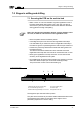
7.3 Functional elements on the plotter head
fig. 35: Side view of plotter head
1
- Valves
9
- High-frequency spindle with pneumatic cylinder
2
- Adjuster for damped travel, upwards
10
- Stop ring
3
- Extraction
11
- Retaining block
4
- Adjuster for damped travel, down-
wards
12
- Pneumatic connection for active auxiliary clamp
5
- Pneumatic block
13
- Active auxiliary clamp
6
- Base plate for motor
14
- Locating screw for working depth limiter
7
- Pneumatic working depth limiter
15
- Setting screw for knurled nut
(Warning - do not move.)
8
- Pneumatic connection for the collet
16
- Compressed air connection
1
2
5
6
10
11
8
9
12
13
14
15
7
16
3
4