
Instruction manual


STP-200/300/400 Series Instruction Manual
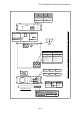
Figure 16.3 External Appearance of the STP Control Unit
Unit : mm
*1
:JIS
508
30440
470
3
430
482.6
33.3
416
33.3
19
68.1
346.4
68.1
7.1
10
112.610
21.988.821.9
132.6
16
11.15 460.3
11.15
41.8
346.4
41.8
26.3
430
26.3
482.6
3.3126
3.3
27.3
78
27.3
10
18
50
309 111
35
10
(150)
(Cable space)
Screw holes for rubber foot M4
*1
(4 pcs.)
c
16-8