
Instruction manual


STP-200/300/400 Series Instruction Manual
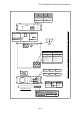
Figure 16.1 External Appearance of the STP Pump (without Anti-Corrosion Treatment) (Example: STP-400)
Unit : mm
*1
:JIS
*2
:
JVIS
Viewed from arrow A
8
50
18
25
φ146
φ180
φ140
MIN 240
A
4
5
゚
101
108
φ
1
6
0
Outlet port flange KF
*1
25
M8
*1
Depth 16
D
C
A
φB
Screw hole for leg
Dimensions List (Total Length of the Pump and Flange)
A
B
C
D
Flange
Model
ICF
*2
152
VG
*1
100
ISO100
STP-200/300 Series
ICF
*2
203
VG
*1
150
ISO160
STP-400 Series
248
248
248 218 218218
180
141
12
12
235
141
203
22
141
12
171
171
171
14
20
152
185
130
1
STP connector
Inlet port flange
(Bending dimensions of the STP connection cable)
(4 pcs.)
16-6