
Specifications


Planning and Engineering Guide, Release TR5.0.x/TN6.0.x 29
Supported
Protected
Topologies
(Summary)
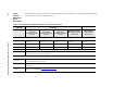
This table summarizes supported topologies and protection schemes for a Traverse
network.
Table 3 Supported Protected Topologies
Topology
Protection Scheme
SONET SDH Gateway
Simple
point-to-point or
linear chain
1+1 APS 1+1 MSP
1+1 Optimized
1+1 MSP <–> 1+1 APS
1+1 MSP <–> UPSR
Ring UPSR
1
2F-BLSR
1
Force10 supports both STS and VT path protection.
SNCP
2
ring
2F MS-SPRing
2
Force10 supports both high order and low order SNCP path protection.
SNCP <–> 1+1 APS
Mesh 1+1 Path
(STS and VT)
SNCP n/a
Single node
interconnected rings
UPSR <–> UPSR
UPSR <–> BLSR
BLSR <–> BLSR
SNCP <–> SNCP
SNCP <–> MS-SPRing
MS-SPRing <–> MS-SPRing
SNCP <–> UPSR
Two node
overlapping rings
UPSR <–> UPSR
UPSR <–> BLSR
BLSR <–> BLSR
SNCP <–> SNCP
SNCP <–> MS-SPRing
MS-SPRing <–> MS-SPRing
n/a
Two node
interconnected rings
UPSR <–> UPSR
UPSR <–> BLSR
BLSR <–> BLSR
SNCP <–> SNCP
SNCP <–> MS-SPRing
MS-SPRing <–> MS-SPRing
UPSR <–> SNCP
Four node
interconnected rings
UPSR <–> UPSR
UPSR <–> BLSR
3
BLSR <–> BLSR
3
3
Drop-and-continue not supported on interconnecting BLSR or MS-SPRing nodes.
SNCP <–> SNCP
SNCP <–> MS-SPRing
3
MS-SPRing <–> MS-SPRing
3
UPSR <–> SNCP
UPSR <–> MS-SPRing
3
BLSR
3
<–> SNCP
BLSR <–> MS-SPRing
3