
Operating instructions


ASSEMBLY
Assembly Section 2-8
CABLE CONTROL LEVER STAND
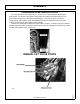
Preassemble the cable control boxes to the cable control bracket as shown in the parts
section. Use the image below for positioning the cable control bracket. Place the front
corner of the support bracket 4” from the inside right window and the rear corner from the
back side as shown below. The base will sit on top of the floor mat. Be sure that the
location of the stand will allow clearance between the cable control box handles and all
existing interior levers, etc. Also watch out for wiring and brackets when placing the bracket
for drilling and cutting.
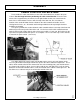
The spacers provided are used to allow the cable control bracket to set on top of the floor mat
while being held securely to the floor of the cab. Use the base of the cable control bracket to
mark the floor mat for cutting. Cut the holes for the spacer with a 1” hole saw. Drill 3 holes for the
capscrews using the bracket and spacers as a template. Then secure with cap-screws and nuts
as noted in the parts section.
(ASM-MF-0006)
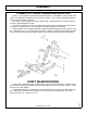
The rubber boot in the corner of the rear window can be cut in a cross hair pattern and if
necessary the bottom cut through to allow it to slip over the cables and back into position. These
cables will be routed to the lift valve mounted on the valve mounting plate, and should not have
any sharp bends or kinks in them. Secure cables with zip ties and apply RTV sealer or similar
product in and around individual cables, inside and outside of the cab for a water tight seal. Do
not allow excess cable to hang unsecured on the outside of the cab.