GB Operating manual Performance Series 450e Airless high-pressure spraying unit Models: 0558067 0558073 Performance Series 450e Edition 9 / 2010 0558 940D
GB Warning! Attention: Danger of injury by injection! Airless units develop extremely high spraying pressures. 1 Never put your fingers, hands or any other parts of the body into the spray jet! Never point the spray gun at yourself, other persons or animals. Never use the spray gun without safety guard. Do not treat a spraying injury as a harmless cut. In case of injury to the skin through coating materials or solvents, consult a doctor immediately for quick and expert treatment.
GB Contents Safety regulations for Airless spraying........................ 4 Earthing instructions.........................................................5 2. 2.1 2.2 General view of application...........................................6 Application........................................................................6 Coating materials..............................................................6 3. 3.1 3.2 3.3 Description of unit..........................................................
Safety Regulations 1. GB Safety regulations for Airless spraying This manual contains information that must be read and understood before using the equipment. When you come to an area that has one of the following symbols, pay particular attention and make certain to heed the safeguard. NOTE TO PHYSICIAN: Injection into the skin is a traumatic injury. It is important to treat the injury as soon as possible. DO NOT delay treatment to research toxicity.
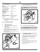
Safety regulations GB General view of application HAZARD: HAZARDOUS VAPORS Paints, solvents, insecticides, and other materials can be harmful if inhaled or come in contact with body. Vapors can cause severe nausea, fainting, or poisoning. HAZARD: EXPLOSION HAZARD DUE TO INCOMPATIBLE MATERIALS Will cause severe injury or property damage. PREVENTION: • Do not use materials containing bleach or chlorine. • Do not use halogenated hydrocarbon solvents such as methylene chloride and 1,1,1 - trichloroethane.
General view of application 2. 2.1 GB General view of application 3. Application 3.1 All painting jobs in the workshop and on the building site, small dispersion work with the spray gun or internally fed Airless roller. Coating materials Processible coating materials i Pay attention to the Airless quality of the coating materials to be processed. 3.2 Dilutable lacquers and paints or those containing solvents, twocomponent coating materials, dispersions, latex paints.
GB 3.3 1 2 3 4 5 6 7 Description of unit Legend for explanatory diagram Performance Series 450e Spray gun High-pressure hose Return hose Suction hose Frame Drip cup Power cord 8 Relief valve Lever position vertical – PRIME ( k circulation) Lever position horizontal – SPRAY ( p) 9 Pressure control knob 10 ON/OFF switch 11 Circuit breaker 12 Pressure gauge 13 Oil cup for Piston Lube (Piston Lube prevents increased wear of the packings) 3.
GB Description of unit 3.5 Technical data Voltage: Max. current consumption: Power cord: Acceptance capacity: Max. operating pressure: Volume flow at 12 MPa (120 bar) with water: Max tip size: Max. temperature of the coating material: Max viscosity: Weight: Special high-pressure hose: Dimensions (L X W X H): Vibration: Starting operation 5. 110 Volt AC, 50/60 Hz 9.5 A @ 110VAC 3 x 1.5 mm2 – 6 m 900 Watt 214 bar (21.4 MPa) Fill the oil cup with Piston Lube (Fig. 3). Do not use too much Piston Lube, i.
GB Spraying Technique 5. Spraying technique Injection hazard. Do not spray without the tip guard in place. NEVER trigger the gun unless the tip is completely turned to either the spray or the unclog position. ALWAYS engage the gun trigger lock before removing, replacing or cleaning tip. 3 The key to a good paint job is an even coating over the entire surface. Keep your arm moving at a constant speed and keep the spray gun at a constant distance from the surface.
Handling the high-pressure hose 6. GB Handling the high-pressure hose 8. Avoid sharp bending or kinking of the high-pressure hose. The smallest bending radius amounts to about 20 cm. Do not drive over the high-pressure hose. Protect against sharp objects and edges. High-pressure hose The unit is equipped with a high-pressure hose specially suited for piston pumps. i 7. 1. Cleaning the unit (shutting down) A clean state is the best method of ensuring operation without problems.
GB 8.2 i Suction filter Cleaning the unit (shutting down) 8.4 Cleaning the Airless spray gun 1. Rinse Airless spray gun with an appropriate cleaning agent. 2. Clean tip thoroughly with appropriate cleaning agent so that no coating material residue remains. 3. Thoroughly clean the outside of the Airless spray gun. A clean suction filter always guarantees maximum feed quantity, constant spraying pressure and problem-free functioning of the unit. 1. Screw off the filter (Fig. 5) from suction pipe. 2.
GB Remedy in case of faults 9. Remedy in case of faults Type of malfunction A. B. C. Unit does not start Unit does not draw in material Unit draws in material, but the pressure does not build up Possible cause Measures for eliminating the malfunction 1. No voltage applied. 1. Check voltage supply. 2. Pressure setting too low. 2. Turn up pressure control knob. 3. ON/OFF switch defective. 3. Replace. 1. Relief valve is set to SPRAY (p spray). 1.
GB Type of malfunction D. E. F. G. Possible cause Remedy in case of faults Measures for eliminating the malfunction Coating material exits at the top of the fluid section 1. Upper packing is worn. 1. Remove and replace packing. 2. Piston is worn. 2. Remove and replace piston. Increased pulsation at the spray gun 1. Incorrect high-pressure hose type. 1. Only use titan original-high-pressure hoses in order to ensure functionality, safety and durability. 2. Tip worn or too large. 2.
GB Servicing 10. 10.1 Servicing 11.2 Danger of crushing - do not reach with the fingers or tool between the moving parts. High-pressure hose 3. Unplug the power plug from the outlet. 4. Remove the retaining clip from the connecting bend at the suction hose and pull off the suction hose. 5. Screw off the return hose. 6. Swivel the unit 90° to the rear in order to work more easily on the material feed pump. 7. Unscrew the inlet valve housing (Fig. 9, Item 1) from the pump manifold. 8.
GB Repairs at the unit 5 8 10 6 10 7 8 4 9 11 12 2 7 11.3 1. 2. 3. 4. 5. 6. 7. Packings 1 Remove inlet valve housing in accordance with the steps in Chapter 11.2, Page 14. It is not necessary to remove the outlet valve. Unscrew both cylinder head screws (Fig. 11, Item 1) from the pump manifold (2) with a 3/8 inch hexagon socket head wrench. Slide the pump manifold (2) and piston (3) forward until the piston is out of the T-slot (10) on the slider assembly (5).
Repairs at the unit 15. 16. 17. 18. 19. 20. 21. 22. 23. 24. 11.4 1. 2. 3. 4. 5. 6. 7. 8. 9. i 10. 11. i 12. 13. GB Guide piston (3) through the lower packings (9) into the pump manifold (2) from below. Using a rubber mallet, lightly tap the piston (3) from below until it can be seen above the pump manifold. Remove installation tool from piston (3). Carefully tighten retainer nut (6) with adjusting wrench. Slide the top of the piston (3) into the T-slot (10) on the slider assembly (4).
GB 11.6 1. 2. 3. 4. 5. i Replacing the Gears 11.7 Open the relief valve, valve position PRIME (k circulation), switch the unit OFF, and unplug the power cord. Loosen and remove the four motor cover screws (Fig. 16. 1). Remove the motor cover (2). Disconnect the black and red wires coming from the gear box housing. Loosen and remove the four motor mounting screws (3). Pull the motor (4) out of the gear box housing (5). 1. 2. 3. 4. 5. 6.
Switch F 1 2 F Brown / black EMI filter Brown / black F F 3 4 Blue / white Blue / white Black Power cord White F Black White F Circuit breaker Brown / Blue for model 0558067. Black / White for model 0558073. + M MB FB Blue Microswitch Blue Black F M Capacitors Black + M WH4 F Red FB MB WH2 F Black Motor F M Red WH5 Red WH7 WH1 WH6 11.
GB Accessories 12. Appendix Accessories for Performance Series 450e Liquid Shield Plus Airless Tip Selection Cleans and protects spray systems against rust, corrosion and premature wear. Now with -25º anti-freeze protection. Part # Description 314-483 4 ounce (112 ml) bottle 314-482 1 liter bottle Tips are selected by the orifice size and fan width.
4343 58 466 110V 0 Ft. Spare parts list Performance Series 450e Main Assembly 13 14 30 15 1 16 17 18 BS4343 NEMA 5-15P 2 19 3 0558 466 ~110V 20 Ft. 800-741 4 ~120V 8.25 Ft. 5 NEMA 5-15P 20 21 10 11 12 6 7 800-741 ~120V 8.25 Ft.
Item Part No. Description Item Part No.
Spare parts list Performance Series 450e Fluid section 1 2 3 24 4 25 5 26 6 7 27 8 9 10 11 12 13 14 15 16 17 18 19 20 21 22 23 22 Performance Series 450e
Item Part No.
Spare parts list Performance Series 450e Drive Assembly 1 2 9 10 3 4 5 8 6 7 Item Part No.
Spare parts list Performance Series 450e Motor Assembly 1 6 7 2 3 4 5 Item Part No.
Spare parts list Performance Series 450e Stand 1 4 2 5 6 3 7 8 9 10 11 Item Part No.
Spare parts list Performance Series 450e Suction system 1 4 2 3 Item Part No.
Warranty Titan Tool, Inc., (“Titan”) warrants that at the time of delivery to the original purchaser for use (“End User”), the equipment covered by this warranty is free from defects in material and workmanship.