
Technical data

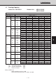


1. Specifications
1
12
3
4
5
I-72
HP
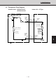
LP
High pressure
switch
Compressor
Low pressure switch
Accumulator
EC
P
Heat exchanger
4-way valve
EC
P
Heat exchanger
Distributor
Electronic
ref.control
valve
Strainer
Liquid line
nipple
Liquid line
service
valve
O.D.
ø9.52mm
(3/8")
O.D.
ø19.05mm
(3/4")
Gas line
nipple
Gas line
service
valve
Distributor
Sub-heat exchanger
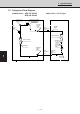
Cooling Cycle
Heating Cycle
Strainer
M
Muffler
1552_C_S
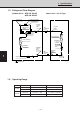
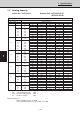
Temperature Indoor air intake temp. Outdoor air intake temp.
Cooling
Maximum 35°C DB / 23°C WB 43°C DB
Minimum 18°C DB / 14°C WB -15 °C DB
Heating
Maximum 27°C DB / — WB 21 °C DB / 15.5°C WB
Minimum 15°C DB / — WB -15°C DB / — WB
1-5 Refrigerant Flow Diagram
Outdoor Units : AER 436 SHL3E
AER 448 SHL3E
Indoor Units : 36, 48 Type
1-6 Operating Range