
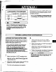
Technical data

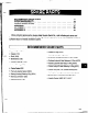
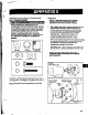
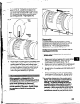

2. Spread bottom of coupling guard half (pump end)
(P+-=-~~
slightly and place over pump end plate as shown
in Fig. C. The annular groove in the guard half is
located around the end plate. See detail drawing,
Fig. E.
I
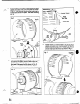
3. After the coupling guard half (pump end) is located
around the end plate, secure it with a bolt, nut
and two (2) washers through the round hole at the
front end of the guard half as shown in Frg. D.
Tighten securely. See detail drawing, Fig. E.
84
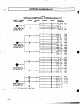
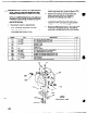
Details:
Fig. E
-
Annular Groove
4. Spread bottom of coupling guard half (driver end)
slightly and place over coupling guard half (pump
end) so that annular groove in coupling guard half
(driver end) faces the motor as shown in Fig. F.
zig.
F
I I
I