
Technical data

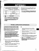

fnstailation Instructions for Goulds
ANSI
615.1
Coupling Guards
Before assembly or disassembly of the
coupling guard is performed the motor must be
de-energized, the motor wntroi~er/starter put in
a iocked-outposition and a caution tag piaced
at the starter indicating the disconnect
Replace coupling guard before resuming
normal operation of the pump. Goulds Pumps,
inc. assumes no liability for avoiding this
prmice. ,; ,I_ ..
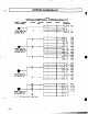
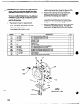
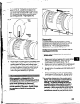
Fig. A
Gil
End Plate
(Driver End) #234A
(Pump End) #234B #5(X B (2 Rqd.)
S-1 6 Nut (3 Reqd.)
3%’ Washer (6 Reqd.)
M-13 x %. Hex Head Bolt (4 Reqd.
%-16x 2’ Hex Head Bolt (3 Reqd.
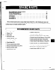
Simplicity of design allows complete assembly of the
coupling guard, including the end plate (pump end), in
about fiieen minutes. If the end plate is already in
place, assembly can be accomplished in about five
minutes.
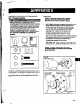
Assembly:
NO7E if end plate (pump end) is already
installed, make
any
necessary wu
adjustments and then proceed to g
Mng
tep 2.
1. XLT-X ONLY Align the end plate (pump end) to the
pump bearing housing so that the large slots on
the end plate clear the bearing housing tap bolts
and the small slots are aligned to the impeller
adjusting bolts. Attach the end plate ‘to the
bearing housing using the jam nuts on the
impeller adjusting bolts as shown in Fig. B.
After the end plate is attached to the bearing housing,
the impeller clearance must be checked and reset
as explained in the Goulds operations and
maintenance manual for your pump.
STX, MTX, LlX - Align end plate (pump end) to the
Bearing Frame. (No impeller adjustment required)
NOTE= Coupling adjustments should be
completed before proceeding with coupling
guard as-b&
Fig. B
six, MTX, LTX
83