
Technical data

ALL MODELS STX, MTX, LTX, XLT-X, X17
I
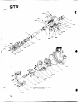
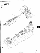
4. Install casing bolts (370), finger tight. Casing bolts
(370)
may be coated with anti-galling compound
Back pull-out assemb/y weighs more than 50
Ibs. Do not handle unassisted as physical
injury may occuf.
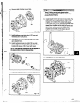
1. Clean casing fit and install casing gasket (351) in
place on seal chamber/stuffing box cover.
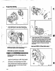
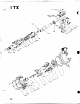
2. Loosen clamping bolts (370C) and jacking bolts
(370D) on bearing housing (Fig. 130).
Fig. 130
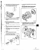
3. Install back pull-out assembly in casing (Fig. 131).
to aid disassembly. Tighten the casing bolts per
Table 9 torque values, page 51. Install casing
jack screws (418), snug tight (Fig. 132).
1 A
CAUTION
-2
Do not overtighten casing jack screws (418).
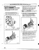
4a. Replace shims under frame foot and tighten frame
foot to bedplate.
To
insure that the proper shim is
used, a dial indicator should be mounted to
measure distance between top of frame and
bedplate. This distance should not change as
frame foot bolting is tightened. .
370
5. Check total travel of impeller in casing. With new
parts acceptable range is 0.030 in. (.76 mm). to
0.066 in. (1.65 mm). If outside this range
improper parts or installation, or too much pipe
strain is present. Determine cause and correct.
6. Adjust impeller clearance according to procedure
outlined in Section 5, Preventive Maintenance.
7. Replace auxiliary piping at this time.
8. Fill pump with proper lubricant. Refer to Section 5,
Preventive Maintenance for requirements.
68