
Technical data

6.
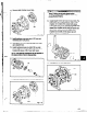
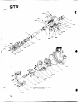
Check impeller runout. Check vane tip to vane tip.
Total indicator reading greater than 0.005 in.
(.13 mm) indicates a problem (Fig. 126).
Fig. 126
7.
install packing and gland according to Section 4,
Operation.
Pumps With Dynamic Seals:
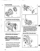
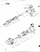
1.
Place backplate (444) flat side down on the bench
(Fig. 127).
n
2. Place repeller (262) in backplate (444), sleeve side
up.
3.
Place teflon gasket (264) on backplate (444), lining
up holes.
4.
Place stuffing box cover (134) on backplate (444),
lining up holes.
5. Install four (4) socket head cap screws (265), tighten
securely.
6.
Install new sealing element into gland.
7. Install gasket (360Q) and gland (107) on stuffing
box cover (184). Install nuts (355).
*\
355
Fig. 127
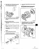
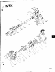
8. Install dynamic seal assembly. Install nuts (370H)
(Fig. 128).
NOTE: Anti-galling compound, can be applied
to the sleeve bore to aid in dkassembly.
Fig. 128
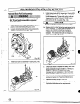
9. Check stuffing box cover run-out. Rotate indicator
through all 360 degrees. Total indicator reading
greater than 0.005 in. indicates a problem
(Fig. 129).
Fig. 129
67