
Technical data

Pumps
Wii Packing:
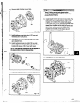
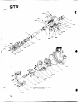
1. Install stuffing box cover (184) with nuts (370H).
Fig. 121
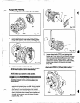
2. Checkstuffqboxcover&t-ouLRotateindii
through 360 degrees Total indicator reading greater
than 0.005 In. (.13 mm) indicates a problem (Fig. 122).
Fig. 122
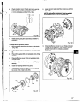
3. Install shaft sleeve (126) (Fig. 123).
NOTE: Anti-galling compound, can be applied
to the sleeve bore to aid in disassembly.
NOTE: Make sure sleeve is fully seated.
Wear a heavy set of work gloves when
handling impeller (101) as sharp edges-may
cause injury.
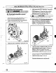
4. install impeller (101) with O-ring (412A). Put shaft
wrench and coupling key on shaft. When impeller
(101) makes firm contact with sleeve (126), raise
shaft wrench (counterclockwise when viewed
from impeller end of shaft) off bench and slam it
down (clockwise when viewed from impeller end
of shaft). A few sharp raps will tighten impeller
properly (Fig. 124).
66
5. Loosen damp bolts (37OC), and jacking bolts
(3700) (Fig. 124). Measure gap between impeller
(101) and seal chamber/stuffing box cover (164)
with a feeler gauge. When 0.030 in. (.76 mm)
clearance is reached, tighten damp bolts (370C).
jacking bolts (37OD), and locking nuts (423)
(Fig. 125).
NOTE: This approximates the impallpr position
when set at 0.015 in. (28 mm) from, casing.
_ _,___. __. _ _ - . - __
. _.-.-