
Technical data

,
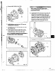
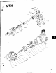
10. Remove Seal chamber cover (184).
Fia. 116
11. Install stationary seat into gland (107) per seal
manufacturers irxtructions.
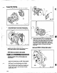
12. Slide gland (107) with stationary seat over shaft,
up to adapter face.
13. install mechanical seal on shaft (122) or shaft
sleeve (126) per seal manufacturers instructions.
Install shaft sleeve (126) if used (with seal).
NOTE: Anti-gallmg compound can be
tie sleeve bore to aid in disassembly.
applied to
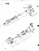
@
0
Fig. 117
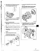
14. Install seal chamber cover (184) with nuts (370H).
118
_ .
Wear a heavy set of work gloves when
handling impeller (107) as sharp edges may
cause physical injury.
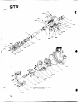
15. Install impeller (101) with new O-ring (412A). Put
shaft wrench and coupling key on shaft. When
impeller (101) makes firm contact with sleeve
(126), raise shaft wrench (counterclockwise when
viewed from impeller end of shaft) off bench and
slam it down (clockwise when viewed from
impeller end of shaft). A few sharp raps will
tighten impeller (101) properly.
Fig. 119
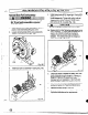
16. Install gland (107) with nuts (355).
107
- 355
Fig. 120
65
_.. .- --.- _
.._ _ _. __.-_-_--m-----~-