
Technical data


P,--.
/_
,,-
!‘.
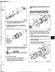
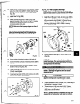
6. Loosen clamp bolts (37OC), and jacking bolts
(3700).
Measure gap between impeller (101) and
seal chamber/stuffing box cover (184) with a
feeler gauge. When 0.030 in. clearance is
reached, tighten clamp bolts (37OC), jacking bolts
(370D), and locking nuts (423) (Fig. 112)
NOTE: This approximates the impeller position
when
set at
0.015 in. (25 mm) from casing.
Final impeller adjustment must be made after
installation into casing. I
Fig. 112
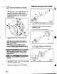
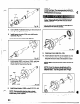
7. Check impeller (101) rut-rout. Check vane tip to vane
tip. If total indicator reading is greater than
0.005 in. (.13 mm), determine cause and correct
before proceeding (Fig. 113).
64
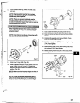
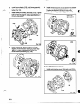
8. Blue the shaft sleeve (126) or shaft (122) if no
sleeve is used. Scribe a mark at gland gasket
face of seal chamber/stuffing box cover (184).
This will be the datum for installation of
mechanical seal (Fig. 114).
-29
Fig. 114
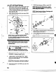
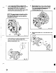
9. Remove the impeller (1 Ol), and shaft sleeve (126)
if used.
. .-._ -_.