
Technical data
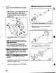
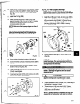


2. Check seal chamber cover run-out. Rotate indicator
through 360 degrees. If total indicator reading is
greater than 0.006 in. (.I3 mm), determine cause
and correct before proceeding (Fig. 109).
Fig. 109
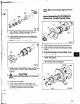
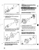
3. Install shaft sleeve (126) if used (Pig. 110).
’ NOTE: Make stira $&a is &fly
seated.
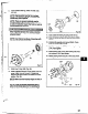
‘- bfeara heavysetof workgloves when- :
handling impeller (101) as sharp edges may
cause physical infury. ,
‘.
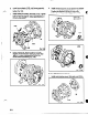
4. STX, MTX, LTX - Install impeller (101) with O-ring
(412A).
4a. XLT-X & Xl7 - instail impeller (101) with O-ring
(412A). Install new tefion washer (42813)) on plug
(458Y) and install in nose of impeller.
Fig. 11 OA
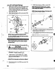
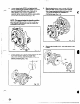
5. Put shaft wrench and coupling key on shaft. When
impeller (101) makes firm contact with sleeve
(126), raise shaft wrench (counterclockwise,
viewed from impeller end of shaft) off bench and
slam it down (dockwise, viewed from impeller
end of shaft). A few sharp raps will tighten
impeller (101) properly (Fig. 111).
, 101
63