
Technical data


6.
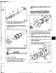
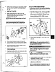
lnstall
frame adapter (108) onto frame assembly.
Align bott holes and dowel locations with those on
frame (Fig. 105).
7. Install dowel pins (4698), and bolts (3708). Tighten
bolts to Table 9, page 51, torque specifications, in
a crisscross pattern.
w 4690
Fig.
105
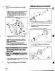
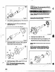
8. Check adapter fiis. Rotate shaft through 360
degrees. If total indicator reading is greater than
.005 in. (.13 mm), determine the cause and
correct before proceeding (Fig. 106).
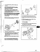
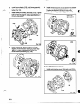
9. Install inboard labyrinth oil seal (333A) into adapter
(108) / bearing frame (228). It is an (O-ring fit.
Position the labyrinth seal drain slots at the
bottom (6 o’dock) position. (Fig. 107A, 1078)
hUX/LTX
XLT-X, Xl 7
333A
I
@
Fig. 107A
Fig. 1078
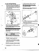
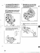
Pumps With Mechanical Seals:
1. Install seal chamber cover (184) with nuts (370H).
Fig. 108
62