
Technical data
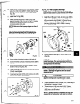


12. Co;to;il internal surfaces of bearing frame (228A)
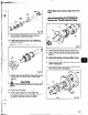
13. Install shaft assembly into frame (228A). Check
shaft for free turning (Fig. 101).
14. Install clamping bolts (370C) into bearing
housing
(134). Hand tighten.
15. install jacking bolts (3700) with locking nuts (423)
into housing (134). Hand tighten.
.
16. Attach bearing frame foot (241) with bolts (37OF).
Hand tighten.
- 370F
Fig. 101
ALL MODELS
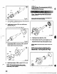
1. Support frame assembly in horizontal position.
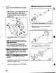
2. Check shaft end play. Move shaft forward then
backward by hand, noting indicator movement. If
total indicator reading is greater than Table 10,
page 51, values, disassemble and determine
cause (Fig. 102).
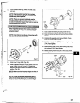
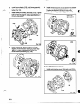
3. Check shaft/sleeve runout. Put on shaft sleeve (126)
if used, and thread on impeller, hand tight. Rotate
shaft 360 degrees. If total indicator reading is
greater then -002 in., disassemble and determine
cause. Remove impeller and shaft sleeve
(Fig. 103).
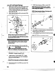
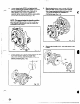
4. Check frame face run out. Rotate shaft so indicator
rides along the fit for 360 degrees. If total indicator
reading is greater than O.OOj in. (.025 mm)
disassemble and determine cause (Fig. 104).
Fig. 101
5. Place manila gasket (3600) on frame (226) (Pig. 105).
NOTE: The gasket is designed to fit me wa
only. The dowel pins (4698)
may be start eJ in
their holes to hold the gasket in place.
61
__._.^