
Technical data


1
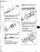
Fig. 96
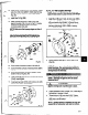
5. Coat outside of outboard bearing (112A) and bore of
bearing housing (734) with oil.
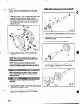
6. Install bearing housing (134) onto shaft/bearing
assembly (Pig. 97).
NOTE: Do not force assembly together.
Fig. 97
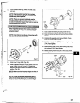
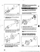
7. install gasket (36OC), end cover (lOgA), and bolts
(371 C). Refer to Table 9 for bolt torque values.
Check shaft for free turning (Fig. 98).
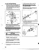
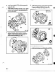
8. Install inboard beating (166A) on shaft (122) (Fig. 99).
,-
NOTE: Regreaseable bearing has a sing16
shield. The inboard bearing is installed with
shield away from impeller.
Fig. 98
60
NOTE: There are several methods used to
instail bearings, The recommended method is
to use an induction heater that heats as wefl as
demagnetizes the bearings
Wear insulated gloves when using a bearing
heater. Bearings will get hot and can cause
physical injuT.
NOTEZ Coat internal surjaces of beatings with
lubricant to be used in service.
Fig. 99
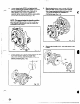
9. Install new O-ring (496) (Fig. 100).
10. Install outboard labyrinth oil seal (332A) into end
cover (109A). It is an O-ring fit Position the
labyrinth seal drain slots at the bottom 6 o’clock
position.
NOTE: Make sure the keyway edges are free of
burrs.
NOTE: Cover the keyway I>hwise with a
piece of ehzctrical tape rior to installin
the
labyrinth seal. This wi I prvtect the O-
P
r?
ngs.
11. Coat outside of bearing housing (134) with oil.
^ _ . - . -
. _
-_
aJ*