
Technical data
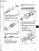
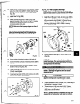


FiQ. 79
9. Coat outside of outboard bearing (112A) and
bearing housing (134A) bore with oil.
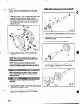
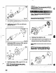
10. Install bearing housing (134) onto shaft/bearing
assembly (Pig. 80).
NOTE: Do not force assembly together.
’
Fia. 80
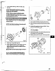
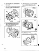
11. Install clamp ring bolts (236A). Check shaft for free
turning. Refer to Table 9 for bolt torque values
(Fig. 81).
I
A
CAUTION
I
77ghten clamp ring bolts (236.4) in a criss cross
pattern.
12. Install new O-ring (496).
13. Install outboard labyrinth oil seal (332A) into
bearing housing (134). It is an O-ring fit. Position
the labyrinth seal drain slots at the bottom
(6 o’clock) position.
tf&E: Make sure the keyway edges are free of
.
NOTE: Cover the keyway IerFgthwise with a
piece of ehzctrical tape prior to installing the
Isbyrinth seal.
This will protect the O-rings.
,
Fig. 81
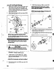
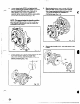
14. Coat outside of bearing housing (134A) with oil.
15. Coat all internal surfaces of bearing frame (228)
with oil.
16. Install shaft assembly into frame (228A). Check
shaft for free turning.
17. Install clamping bolts (370C) into bearing housing
(134A). Hand tighten.
18. Install jacking bolts (370D) with locking nuts (423)
into housing (134A). Hand tighten.
Fig. 82
55
_- ___. . . . . . I . .
---__I__.P...-~-.s--?--.~,~~
. ,-.“..-l-- -m. -
i+r~..Le--.-- ..-- --
_- ., _ .-
~