
Technical data
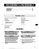

228. DISASSEMBLY OF POWER END - LTX
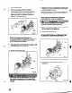
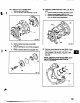
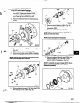
1. Remove clamp screws (37OC). Back off jam
nuts (423). Tighten jack screws (3700)
evenly, this will start bearing housing (134)
out of bearing frame (228A) (Fig. 41).
2. Remove shaft assembly from bearing frame
(228A).
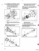
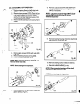
3. Remove jack screws (370D) with nuts (423)
(Fig. 42).
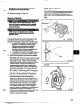
4. Remove clamp ring screws (236A). Separate
clamp ring (2536) from bearing housing (134)
NOTE: Clamp ring cannot be removed from the
shaft until bearings are removed.
Fia. 42
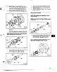
5. Remove bearing housing (134) from shaft (122)
with bearings (112A, 168A) (Fig. 43A).
6. Remove bearing housing O-ring (469).
Fig. 43A
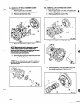
7. Remove inboard bearing (168A) (Fig. 43B).
8. Remove bearing locknut (136) and bearing
lockwasher (382).
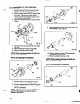
9.
Remove outboard bearings (112A). Remove
clamp ring (2538)
NOTE:
When pressing bearings off shaft, use
force on inner race on/y.
NOTE: Save bearings for inspection.
Do not
reuse bearings.
NOTE: 50 not remove oil ffinger (248.A) unless it
is damaged.
Fig. 43E
10. Remove outboard labyrinth seal (332A) from
bearing housing (134). Remove O-rings
(497f3 (497G)
if necessary (Fig. 44).
NOTE: Labyrinth oil seal O-rings (497F, G) are
part of 3196 maintenance kits of can be
obtained separately