
Technical data

NO775 Blue and s&be shaft for relocating
coupling hub during reassembly.
I
\
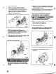
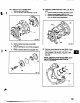
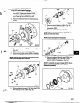
16. Remove coupling hub (Fig. 24).
Removal of Impeller
Never apply heat to remove impeller. Use of
heat may cause an explosion due to trapped
fluid, resulting in seven3 physical Injury and
property damage.
Wear heavy work gloves when handling
impeler (101) as sharp edges may cause
.. physkalinjuty.
Two special features have been incorporated into the
XLT design to ease maintenance problems and
preclude the temptation to apply heat to stubborn parts.
1. A plug has been added to the nose of the XLT
impellers. It is sealed with a teflon gasket
Removing the plug relieves any pressure
between the impeller and the shaft and
provides means to introduce penetrating oil to
,P-
the threads to ease impeller removal.
2. A hexagonal nut is cast on the impeller hub so a
socket wrench can be used to assist removal.
17.
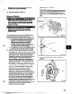
Recommended removal procedure is as follows:
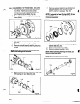
STX, MTX, LTX: Remove impeller (101) from shaft
(122). Slide Goulds shaft wrench (A051 07A) over
shaft (122) and key. Rotate impeller clockwise
(viewed from impeller end of shaft) raising wrench
off work surface. Quickly turn impeller (101)
counterclockwise (viewed from impeller end of
shaft) impacting wrench handle on workbench or
solid block until impeller (101) loosens (Fig. 25).
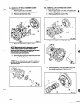
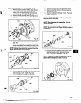
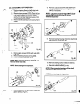
XLT-X & Xl 7: Remove plug (458Y) from front of
impeller (101) and discard teflon gasket (428D)
(Fig. 25A). Spray penetrating oil through plug
hole into cavity at end of shaft. Wait 15 minutes.
Rotate shaft several times while waiting to
distribute oil. Proceed to remove impeller from
shaft as described above for SIX, MlX, and LTX.
If impeller cannot be loosened after several tries,
place socket wrench over cast nut on impeller
hub and turn impeller counterclockwise (viewed
from impeller end of shaft). Be sure impeller
wrench is resting on workbench or solid block and
the powerend is secure on workbench. It is
further recommended that the frame foot (241) be
clamped to the workbench when using this
method to remove the impeller.
NOTE: FOR ALL MODELS
If the impeller cannot be removed by the previous
methods, cut the shaft between the gland and the
frame, remove the impeller, stuffing box cover,
gland, sleeve and shaft end as a unit. Do not use
heat.
I
I
101
Fig. 25 1
Fia. 25A
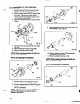
18. Remove impeller O-ring (412A) and discard
(Fig. 26).
37