
Technical data
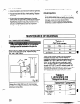

IMPELLER CLEARANCE SETTING
1
Lo&out driver power to prevent accidental
startup and physical injury.
A change in pump performance may be noted over
time by a drop in head or flow or an increase in power
required. Performance can usually be renewed by
adjusting the impeller clearance. Two techniques are
given to set the impeller clearance, the dial indicator
method and the feeler gauge method.
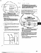
DIAL INDICATOR METHOD
I ‘-
’ 2.
3:
4.
6.
7.
8.
9.
10.
Remove coupling guard. Refer to coupling guard
instructions Appendix II.
Remove coupling.
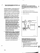
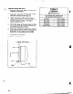
Set indicator so that button contacts either the shaft
end or against face of coupling (Fig. 19).
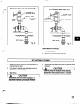
Loosen jam nuts (4238) on jack bolts (371A) and
back bolts out about two turns.
Tighten each locking bolt (370C) evenly, drawing
the bearing housing (134A) towards the bearing
frame (228) until impeller contacts the casing.
Turn the shaft to ensure contact is made.
Set indicator to zero and back locking bolt (370C)
out about one turn.
Thread jack bolts (371A) in until they evenly contact
the bearing frame. Tighten the jack bolts evenly
(about one flat at a time) backing the bearing
housing (134A) away from the bearing frame until
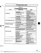
the indicator shows the proper clearance per
Table 3.
Evenly tighten locking bolts (37OC), then jack bolts
(371A) keeping indicator reading at proper
setting.
Check shaft for free turning.
Replace coupling guard.
DIAL INDICATOR METHOD
Fig. 19