
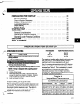
Technical data

COUPLE PUMP AND DRIVER
Lock out driver power to prevent accidental
rotation and physical injury.
1.
Install and lubricate coupling per manufacturer’s
instructions.
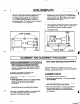
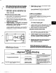
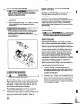
2. Install coupling guard (Fig. 12). Refer to Coupling
Guard Installation and Disassembly Section
(Appendix II).
Never operate a pump without coupling guard
properly installed. Refer to Appendix I1 for
coupling guard installation instructions.
Personal injury will occur if pump is run without
coupling guard.
LUBRICATING BEARINGS
Fig. 12
I A
CAUTION
Pumps are shipped without oil.
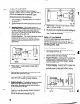
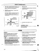
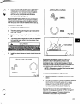
Oil Lubrication: Fill bearing frame with oil, through
filler connection (located on top of bearing frame refer
to Fig. 188) until oil level reaches the middle of the
sight-glass . A high
quality
turbine type oil, with rust
and oxidation inhibitors should be used.
Pure Oil Mist Lubrication: Oil mist is an optional
r”l feature for the 3196. Follow oil mist generator
manufacturer’s instructions. The inlet connections are
located on the top of the bearing frame, connection
points are covered under lubrication. (Refer to
Apprendix I on converting lubrication).
22
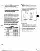
Grease Lubrication: Pumps are shipped with
grease. See Table 6.
Greased For Life Bearings: These bearings are
filled with grease and sealed by the bearing
manufacturer.
If pump is put into operation after prolonged
shut-down, flush out bearings and bearing frame with
a light oil to remove contaminants. During flushing
rotate shaft slowly by hand. Finally, flush bearing
housing with proper lubricating oil to insure oil quality
after cleaning.
See Preventive Maintenance section for lubrication
recommendations.
Operation of the unit without proper lubrication
will cause bearing failure, and pump seizure.
SHAFT SEALING
Mechanical Seal Option: Pumps may be shipped
with or without mechanical seals installed. A. common
seal with this model is the cartridge type. Cartridge
seals are preset at the seal manufacturer’s facility and
require no field settings. Cartridge Seals installed by
the user require removal of the holding clips prior to
operation, allowing the seal to slide into place. If the
seal has been installed in the pump at the Goulds
factory, these clips have already been removed. For
other types of mechanical seals, refer to the seal
manufacturer’s instructions for installation and setting.
Connection of Sealing Liquid: For satisfactory
operation, there must be a liquid film between seal
faces to lubricate them. Refer to seal manufacturer’s
drawing for location of taps. Some methods which
may be
used to
flush/cool the seal are:
a. Product Flushing - In this arrangement, the
pumpage is piped from the casing (and cooled in
an external heat exchanger when required) then
injected into seal gland.
b. External Flush - A clean, cool compatible liquid is
injected from an outside source directly into seal
gland. Flushing liquid must be at a pressure 5-15
PSI (0.35-l .Ol kg/cm*) greater than the stuffing
box/seal chamber pressure. Injection rate should
be V2-2 GPM (2-8 LPM).