
Technical data
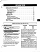

PREPARATION FOR START-UP ...................... .21
Checking Rotation ............................. .21
Check Impeller Clearance ......................... .21
Couple Pump and Driver ......................... -22
Lubricating Bearings ............................ .22
Shaft Sealing ............................... .22
Priming Pump ............................... .24
STARTING PUMP .............................. .25
OPERATION ................................. .26
General Considerations ...........................
.26
Operating at Reduced Capacity ......................
.26
Operating under Freezing Conditions
....................
.26
SHUTDOWN ................................. .26
FINAL ALIGNMENT .............................
.26
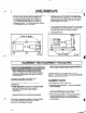
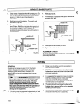
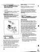
PREPARATION FOR START-UP
,.e-.. CHECKING ROTATING
: f .
\*,
1 A
CAUTION
I
Serious damage may result if pump is run in the
vong robtion.
1. Lo& out power to driver.
Lock out driver power to prevent accidental
start-up and physical injury.
2. Make sure coupling hubs are securely fastened to shafts.
NOTE= Pump is shipped with coupling spacer
removed.
3. Unlock driver power.
4. Make sure everyone is clear. Jog driver just long
enough to determine direction of rotation. Rotation
must correspond to arrow on bearing housing.
5. Lock out power to driver.
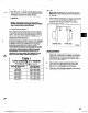
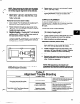
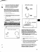
CHECK IMPELLER CLEARANCE
Prior to starting the pump the impeller clearance must
be checked. The pump efficiency is maintained when
the proper impeller clearance is set. The optimum
hydraulic performance is attained by setting the
impeller front clearance at the factory to
’ -3redetermined limits which are consistent with service
a
sonditions.
Frame Designation lmpler Front Clearance Inch (mm)
STX ,005 (.13)
Mix, LTX .cQ8 (20)
XLTX, Xl 7 .015 (36)
The maximum impeller setting should not be set more
than .005 inch (0.13mm) above values in table or
significant performance degradation will result.
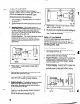
Also, for pumpage temperatures above 200 degrees
F (93 degrees C) the cold (ambient) setting must be
increased per Table 3. This is necessary to prevent
the impeller from contacting the casing due to
differential expansion from the higher operating
temperatures. See Preventative Maintenance section
(58mm) 3”
(.64mm) 5”