
Technical data
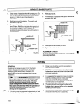

NOTE: Equa/ amounts of shims must be added
.F---
to or removed from each driver foot. Otherwise
the vertic?l angular alignment will be affected.
4.
Repeat steps 1 through 3 until indicator P reads
within .002 in. (.05 mm) or less when hot, or per
Table 1 when cold.
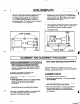
Horizontal Correction (Side-to-Side)
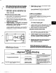
1. Zero indicator P on the left side of coupling half Y,
90” from top dead center (9 o’clock).
2. Rotate indicators through top dead center to the
right side, 180” from the start (3 o’clock). Observe
needle and record reading.
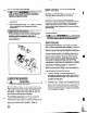
3. Negative Reading
- Coupling half Y is to the left of
coupling half X. Correct by sliding driver evenly in
the appropriate,direction (Fig. 88).
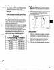
Positive Reading
- Coupling half Y is to the right of
coupling half X. Correct by sliding driver evenly in
the appropriate direction.
Fia. 88
NOTE: Failure to slide motor evenly will affect
horizontal angular correction.
4.
Repeat steps 1 through 3 until indicator P reads
.002
in. (.05 mm) or less.
5. Re-check both horizontal and vertical readings to
ensure adjustment of one did not disturb the
other. Correct as necessary.
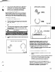
COMPLETE ALIGNMENT
A unit is in complete alignment when both
indicators
A (angular) and P (parallel) do not vary by more than
.002 in. (.05 mm) as measured at four points
90’ apart.
Vertical Correction (Top-to-Bottom)
.l. Zero indicators A and P at top dead center
(12 o’clock) of coupling half Y.
2. Rotate indicator to bottom dead center (6 o’clock).
Observe the needles and record the readings.
3. Make corrections as outlined previously,
Horizontal Correction (Side-to-Side)
1.
Z&o indicators A and P on the left side of coupling
half Y, 90’ from top dead center (9 o’clock).
2. Rotate indicators through, top dead center to the
right side, 180” from the start (3 o’clock). Observe
the needle, measure and record the reading.
3. Make corrections as outlined previously.
4. Recheck both vertical and horizontal readings to
ensure adjustment of one did not disturb the
other. Correct as necessary.
NOTE: With experience, fhe installer will
understand the interaction between angular and
parallel and will make corrections appropriately.
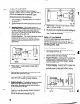
Table 2
Alignment Trouble Shooting
PROBLEM
Cannot obtain horizontal (Side-to-Side)
alignment, angular of parallel
PROBABLE CAUSE
Driver feet bolt bound.
Baseplate not leveled
properly, probably twisted.
REMEDY
Loosen
pump hold down bolts and slide pump
and driver until horizontal alignment is
acheived.
Determine which comer(s) of the baseplate are
high or low and remove or add shims at the
appropriate comer(s) and realign.
Cannot obtain vertical (Top-to-Bottom) alignment,
angular or parallel
Baseplate not leveled
properly, probably bowed.
Determine if center of baseplate should be
raised or lowered and correct by evenly adding
or removing shims at the center of the
17