
Technical data
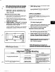

ANGULAR ALIGNMENT
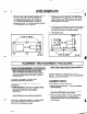
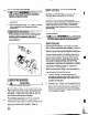
A unit is in angular alignment when indicator A
(Angular indicator) does not vary by more that ,002 in.
(.05 mm) as measured at four points 90” apart.
Vertical Correction (Top-to-Bottom)
1. Zero indicator A at top dead center (12 o’clock) of
coupling half Y.
2. Rotate indicators to bottom dead center (6 o’clock).
Observe needle and record reading.
4.
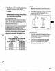
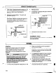
3. Negative Reading
- The coupling halves are
further apart at the bottom than at the top. Correct
by either raising the driver feet at the shaft end
5
(add shims) or lowering the driver feet at the other
end (remove shims), (Fig. 7A).
Fig. 78
Repeat steps 1 through 3 until indicator A reads
.002
in. (.05 mm) or less.
Recheck both horizontal and vertical readings to
ensure adjustment of one did not disturb the
other. Correct as necessary.
Positive Reading -
The coupling halves are closer at
PARALLELAUGNMENT
the bottom than at the top. Correct by either
lowering the driver feet at the shaft end (remove A unit is in parallel alignment when indicator P
(parallel indicator) does not vary by more than .002 in.
(.05 mm) as measured at four points 90’ apart at
operating temperature. Note the preliminary vertical
cold setting criteria, Table 1.
shims) or raising the driver feet at the other end
(add shims).
SHIMS
Fig. 7A
. - . .
4.
nepeat steps
l-3
untrl indicator A reads .002 in
(.05
mm) or less.
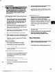
Horizontal Correction (Side-to-Side)
1. Zero indicator A on left side of coupling half Y, 90”
from top dead center (9 o’clock).
2. Rotate indicators through top dead enter to the right
side, 180” from the start (3 o’clock). Observe
needle and record reading.
3. Negative Reading
- The coupling halves are further
apart on the right side than the left. Correct by
either sliding the shaft end of the driver to the left
or the other end to the right.
Positive Reading
- The coupling halves are closer
together on the right side than the left. Correct by
either sliding the shaft end of the driver to the
right or the other end to the left (Fig. 78).
16
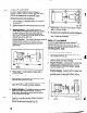
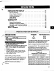
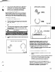
Vertical Correction (Top-to-Bottom)
1. Zero indicator P at top dead center of coupling
(12 o’clock) half Y (Fig. 6).
2. Rotate indicator to bottom dead center (6 o’clock).
Observe needle and record reading..
3. Negative Reading
- Coupling half X is lower than
coupling half Y. Correct by removing shims of
thickness equal to half of the indicator reading
under each driver foot.
Positive Reading
- Coupling half X is higher than
coupling half Y. Correct by adding shims of
thickness equal to half of the indicator reading
from each driver foot (Fig. 8A).
__ .-. _.._,.______.__
kl#
#El
ud
SHIMS
Fig. 8A